
Manual

HV-WP/HW-WP Series Page 31
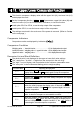
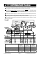
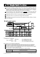
11. Upper/Lower Comparator Function
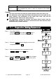
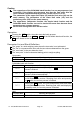
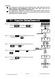
Step 5 If either of f6 0 , f6 2 , f6 4 , f6 6 has been
selected, press the SET switch to use the
comparator.
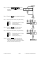
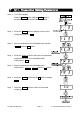
Step 6 Press the MODE switch to display the blinking HI.
Step 7 Set the upper limit value by using the following
switches.
∧ switch Selecting the number of a figure.
< switch Selecting a figure.
F switch Selecting the polarity (+,-).
Step 8 Press the ENTER switch to store the new
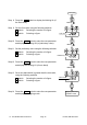
parameter and display the blinking LO.
Step 9 Set the lower limit value by using the following
switches.
∧ switch Selecting the number of a figure.
< switch Selecting a figure.
F switch Selecting the polarity (+,-).
Step 10 Press the ENTER switch to store the new
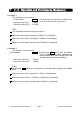
parameters and display the weighing mode.
If the lower limit value is greater than the upper
limit value, the scale returns to step 7.
Last page
LO
HI
,
Upper limit value
,
Blinking
Blinking
,
Lower limit value
,
Weighing value and
comparison result
f6 0
,
f6 2
f6 4
,
f6 6
Either parameter is selected.