iDRA Controller DIN Rail Temperature/Process with Isolated Analog Output Operator’s Manual ® NEWPORT Electronics, Inc. http://www.newportUS.
Additional products from ® NEWPORT Electronics, Inc. Counters Frequency Meters PID Controllers Clock/Timers Printers Process Meters On/Off Controllers Recorders Relative Humidity Transmitters Thermocouples Thermistors Wire Rate Meters Timers Totalizers Strain Gauge Meters Voltmeters Multimeters Soldering Iron Testers pH pens pH Controllers pH Electrodes RTDs Thermowells Flow Sensors For Immediate Assistance In the U.S.A.
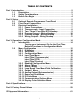
TABLE OF CONTENTS Part 1: Introduction............................................................................................2 1.1 Description .................................................................................2 1.2 Safety Considerations ...............................................................3 1.3 Before You Begin .......................................................................4 Part 2: Setup...................................................................................
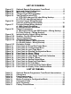
LIST OF FIGURES: Figure 2.1 Figure 2.2 Figure 2.3 Figure 2.4 Figure 2.5 Figure 2.6 Figure 2.7 Figure 2.8 Figure 2.9 Figure 2.10 Figure 2.11 Figure 2.12 Figure 2.13 Figure 3.1 Figure 3.2 Figure 3.3 Figure 3.4 Figure 3.5 Figure 3.6 Figure 3.7 Figure 3.8 Figure 3.9 Figure 3.10 Figure 3.11 Figure 3.12 Figure 3.13 Optional Remote Programmer Front Panel ............................ 5 Input and Output Connections .................................................6 Main Power Connections ...........................
NOTES, WARNINGS and CAUTIONS Information that is especially important to note is identified by following labels: • NOTE • WARNING or CAUTION • IMPORTANT • TIP NOTE: Provides you with information that is important to successfully setup and use the Programmable Digital Meter. CAUTION or WARNING: Tells you about the risk of electrical shock. CAUTION, WARNING or IMPORTANT: Tells you of circumstances or practices that can effect the instrument’s functionality and must refer to accompanying documents.
PART 1 INTRODUCTION 1.1 Description This device can be purchased as a controller, with outputs or as a signal conditioner. • The iSeries offers unparalleled flexibility in process measurement. Each unit allows the user to select the input type, from 10 thermocouple types (J, K, T, E, R, S, B, C, N and J DIN), Pt RTDs (100, 500 or 1000 Ω, with either 385 or 392 curve), DC voltage, or DC current.
1.2 Safety Considerations This device is marked with the International Caution Symbol. It is important to read this manual before installing or commissioning this device as it contains important information relating to Safety and EMC (Electromagnetic Compatibility). This instrument is a panel mount device protected in accordance with EN 61010-1:2001, electrical safety requirements for electrical equipment for measurement, control and laboratory.
1.3 Before You Begin Inspecting Your Shipment: Remove the packing slip and verify that you have received everything listed. Inspect the container and equipment for signs of damage as soon as you receive the shipment. Note any evidence of rough handling in transit. Immediately report any damage to the shipping agent. The carrier will not honor damage claims unless all shipping material is saved for inspection.
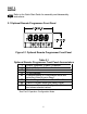
PART 2 SETUP Refer to the Quick Start Guide for assembly and disassembly instructions. 2.1 Optional Remote Programmer Front Panel Figure 2.1 Optional Remote Programmer Front Panel Table 2.
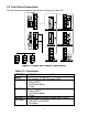
2.2 Front Panel Connections 1 2 3 4 5 6 7 8 9 10 The front panel connections are shown in Figures 2.2 and 2.3. Figure 2.2 Input and Output Connections Table 2.
2.3 Electrical Installation 2.3.1 Power Connections Caution: Do not connect power to your device until you have completed all input and output connections. Failure to do so may result in injury! Connect the main power connections as shown in the figure below. * See Specification Section Figure 2.3 Main Power Connections Table 2.
2.3.2 Thermocouple Input The figure below shows the wiring hookup for any thermocouple type. For example, for Type K hookup, connect the yellow wire to the "2" terminal and the red wire to the "1(-)" terminal. When configuring your controller, select Thermocouple and Thermocouple Type in the Input Type menu (see Part 3). Figure 2.4 Thermocouple Wiring Hookup Table 2.
2.3.3 Two/Three/Four-Wire RTD Figure 2.5 a) RTD-1000 ohm and 500 ohm Wiring Hookup 4-WIRE 3-WIRE 2-WIRE 4-WIRE 3-WIRE 2-WIRE The figures below show the input connections and input connector jumpers (shown in bold lines) required to hookup a 2-, 3- or 4-wire RTD. b) RTD-100 ohm Wiring Hookup The two-wire connection is simplest method, but does not compensate for lead-wire temperature change and often requires calibration to cancel lead-wire resistance offset.
2.3.4 Process Current The figure below shows the wiring hookup for Process Current 0 – 20 mA. 0-20 mA Internal Excitation 0-20 mA External Excitation Figure 2.6 Process Current Wiring Hookup (Internal and External Excitation) When configuring your instrument, select Process Type in the Input Type Menu (see Part 3). 2.3.5 Process Voltage The figure below shows the wiring hookup for Process Voltage 0 – 100 mV, 0 – 1 V, 0 – 10 V. RL 1 V or 10 V 1 V or 10 V 100 mV 100 mV Return Return Figure 2.
2.3.6 Wiring Outputs C OUTPUT 1 OUTPUT 2 OUTPUT 1 OUTPUT 2 This meter has three factory installed outputs. Output 1 can be configured as Control Output or Alarm Output with SPDT Mechanical Relay, SPST Solid State Relay, or Pulse. Output 2 is an Alarm Output with SPDT Mechanical Relay, SPST Solid State Relay, or Pulse. Output 3 is Isolated Analog (retransmission) Voltage and Current Output. Connections are shown below. 0.5 A (T) SSR NO External Load C NC RELAY NO 3 A (T) External Load Figure 2.
This device has snubber circuits designed to protect the contacts of the mechanical relays when it switches to inductive loads (i.e. solenoids, relays). These snubbers are internally connected between the Common (C) and Normally Open (NO) relay contacts of Output 1 and Output 2.
This device may have a programmable serial communication output. The RS-232 and RS-485 Output Connections are shown below. Tx Rx RTN -Tx / Rx +Tx / Rx Figure 2.12 Serial Communication a) RS-232 Output Wiring Hookup b) RS-485 Output Wiring Hookup This device has built-in excitation. The connections are shown below. - Excitation is not available if communication (-C24) or low power (-DC) option is installed. 24 Vdc + Figure 2.
PART 3 OPERATION: Configuration Mode 3.1 Introduction The following configuration section is explained by using the Optional Remote Programmer Display, you may also configure your device on your computer using the Serial Communications Option. The instrument has two different modes of operation. The first, Run Mode, is used to display values for the Process Variable, and to display or clear Peak and Valley values.
3.2 Menu Configuration It is required that you put the controller in the Standby Mode for any configuration change other than Setpoints & Alarms. Figure 3.
3.2.1 ID Number SEE ID MENU SELECTION IN CONFIGURATION SECTION FOR ENABLE/DISABLE OR CHANGE ID CODE. If ID Code is Disabled or set as Default (0000) the menu will skip ID step to Set Point Menu. If ID Code is set to Full Security Level and user attempts to enter the Main Menu, they will be prompted for an ID Code. If ID Code is set to Setpoint/ID Security Level and user attempts to enter the Configuration Menu, they will be prompted for an ID Code. ENTERING YOUR NON-DEFAULT FULL SECURITY ID NUMBER.
3.2.2 Set Points SETPOINT 1: Press a Press d 1) Press a, if necessary until SP1 prompt appears. 2) Display shows previous value of “Setpoint 1” with 1st digit flashing. Press b & c 3) Press b and c to increase or decrease Setpoint 1 respectively. Holding b & c buttons down for approximately 3 seconds will speed up the rate at which the set point value increments or decrements. Press b & c 4) Continue to use b and c to enter your 4-digit Setpoint 1 value.
3.2.3 Configuration Menu Figure 3.2 Flow Chart for Configuration Menu Enter Configuration Menu: Press a Press d Press a 1) Press a, if necessary, until CNFG prompt appear. 2) Display advance to INPT Input Menu. 3) Pressing and releasing a to scroll through all available menus of Configuration section. 3.2.4 Input Type Menu Figure 3.
Input Type (Thermocouple) ENTER INPUT TYPE MENU: Press a Press d Press d 1) Press a, if necessary, until CNFG prompt appears. 2) Display advance to INPT Input Menu. 3) Display flashes T.ç , RTD or PROC (Thermocouple, RTD or Process). If the displayed input type is T.ç , press a to skip to step 6 (T.ç stops flashing). THERMOCOUPLE SUBMENU: Press b Press d Press d Press b Press d 4) Scroll through the available selection to T.ç (flashing). 5) Display shows STRD stored message momentarily and then T.
Input Type (RTD) ENTER INPUT TYPE MENU: Press a Press d Press d 1) Press a, if necessary, until CNFG prompt appears. 2) Display advances to INPT Input Menu. 3) Display flashes T.ç, RTD or PROC (Thermocouple, RTD or Process). If the displayed input type is RTD , press a to skip to step 6 (RTD stops flashing). RTD SUBMENU: Press b Press d Press d Press b Press d 4) Scroll through the available selection to RTD (flashing). 5) Display shows STRD stored message momentarily and then RTD (not flashing).
Input Type (Process) ENTER INPUT TYPE MENU: Press a 1) Press a, if necessary, until CNFG prompt appears. Press d 2) Display advance to INPT Input Menu. Press d 3) Display flashes T.ç, RTD or PROC (Thermocouple, RTD or Process). If the displayed input type is PROC, press a to skip to step 6 (PROC stops flashing). PROCESS SUBMENU: Press b 4) Scroll through the available selection to PROC (flashing). Press d 5) Display shows STRD stored message momentarily and then PROC (not flashing).
ENTER READING CONFIGURATION MENU: Press a Press d Press a Press d 1) Press a, if necessary, until CNFG prompt appears. 2) Display advances to INPT Input Menu. 3) Display advances to RDG Reading Configuration Menu. 4) Display advances to DEC Decimal Point. DECIMAL POINT SUBMENU: Press d Press b Press d 5) Display flashes previous selection for Decimal location. 6) Scroll though the available selections and choose Decimal location: FFFF or FFF.F (also FF.FF and F.
Reading Configuration (If Process was selected) INPUT/READING (SCALE AND OFFSET) SUBMENU: Input Voltage or Current can be converted or scaled into values appropriate for the process or signal being measured. So, a reading may be displayed, for example, in units of weight or velocity instead of in amperes or volts. The instrument determines Scale and Offset values based on two user-provided input values entered with the corresponding readings.
Conversion number is a coefficient of conversion between input values and real full display range (10000 counts, shown as 9999). See Table 3.2 below for proper conversion number. Table 3.2 Conversion Table RANGE 100 mV 1V 10 V 0 -20 mA Example 0-1V In 1 Rd 1 Inp 2 Rd 2 CONVERSION NUMBER 10000 / (100 x 1) = 100 10000 / (1000 x 1) = 10 10000 / (1000 x 10) = 1 10000 / (20 x 1) = 500 = = = = = = 0 - 100.0 0 0 9999 100.
3.2.6 Alarm 1 This unit is equipped with three physical outputs that can only be configured as follows: a) Alarm 1, Alarm 2 & Analog Output b) Output 1, Alarm 2 & Analog Output Alarm must be DISABLED if Ramp is ENABLED. Figure 3.5 Flow Chart for Alarm 1 ENTER ALARM 1 MENU: Press a Press d Press a Press d 1) Press a, if necessary, until CNFG prompt appears. 2) Display advances to INPT Input Menu. 3) Press a, if necessary, until Display advances to ALR1 Alarm 1 Menu.
ALARM 1 ENABLE/DISABLE SUBMENU: Press b Press d 5) Scroll though the available selection until ENBL displays to use Alarm 1. 6) Display shows STRD stored message momentarily and then advances to ABSo only, if it was changed, otherwise press a to advance to ABSo Alarm 1 Absolute/Deviation Submenu. If DSBL Alarm 1 Disabled was selected, all submenus of Alarm 1 Menu will be skipped and meter advances to ALR2 Alarm 2 Menu.
CONTACT CLOSURE SUBMENU: Press d 11) Display flashes previous selection. Press b to N.ç. Normally Closed or N.o. Normally Open. Press d 12) Display shows STRD stored message momentarily and then advances to AçTV only, if it was changed, otherwise press a to advance to AçTV Active Submenu. Normally Open: If this feature is selected, then the relay is "energized" only when an alarm condition occurs. Normally Closed: "Fail Safe" Mode.
ALARM ENABLE/DISABLE AT POWER ON: Press d Press d 15) Display flashes previous selection. Press b to ENBL enable or DSBL disable. 16) Display shows STRD stored message. momentarily and then advances to ALR.L only, if it was changed, otherwise press a to advance to the ALR.L Alarm 1 Low Value Submenu. If the alarm is enabled at Power On, the alarm will be active right after reset. If the alarm is disabled at Power On, the alarm will become enabled when the process value enters the non alarm area.
3.2.7 Alarm 2 This unit is equipped with three physical outputs that can only be configured as: a) Alarm 1, Alarm 2 & Analog Output b) Output 1, Alarm 2 & Analog Output Alarm must be DISABLED if Ramp is ENABLED. Figure 3.6 Flow Chart for Alarm 2 ENTER ALARM 2 MENU: Press a Press d Press a Press d 1) Press a, if necessary, until CNFG prompt appears. 2) Display advances to INPT Input Menu. 3) Press a, if necessary, until Display advances to ALR2 Alarm 2 Menu.
3.2.8 Loop Break Time/Field Calibration It is required that you put the controller in the Standby Mode for any configuration change other than Set Points & Alarms. Figure 3.7 Flow Chart for Loop Break Time/Field Calibration ENTER LOOP BREAK TIME MENU: Press a Press d Press a Press d 1) Press a, if necessary, until CNFG prompt appears. 2) Display advances to INPT Input Menu. 3) Press a, if necessary, until Display advances to LOOP Loop Break Time Menu.
READING ADJUST SUBMENU: Press d 10) Display flashes 1st digit of previous reading adjust value. Press b & c 11) Press b and c buttons to enter a new Reading Adjust value (-1999 to 9999). Press d 12) Display shows STRD stored message momentarily and then advances to SP.DV Setpoint Deviation Menu. Reading Offset Adjust allows the user to fine tune a minor error of the transducer, however some applications may require a large offset adjust. (Displayed Process Value = Measured Process Value ± R.ADJ).
3.2.9 Output 1 This unit is equipped with three physical outputs that can only be configured as follows: It is required that you put a) Alarm 1, Alarm 2 & Analog Output the controller in the b) Output 1, Alarm 2 & Analog Output Standby Mode for any configuration change other than Set Points & Alarms. Figure 3.
ENTER OUTPUT 1 MENU: Press a Press d Press a Press d 1) Press a, if necessary, until CNFG prompt appears. 2) Display advances to INPT Input Menu. 3) Press a, if necessary, until Display advances to OUT1 Output 1 Menu. 4) Display advances to SELF Self Submenu. SELF SUBMENU: The Self Option allows the output of the instrument to be controlled manually from the front panel. Press d Press b Press d 5) Display flashes the current setting of Self, ENBL Enabled or DSBL Disabled.
MAXIMUM/PERCENT HIGH SUBMENU: Specify in percent, the maximum value (99) for control output. If the output is time proportional (Relay, SSR, or Pulse), then the maximum duty-cycle, in percent, is specified. Press d 12) Display flashes 1st digit of previous “Percent High” setting. Press b & c 13) Use b and c buttons to enter a new value for “Percent High”. Press d 14) Display shows STRD stored message momentarily and then advances to CTRL Control Type Submenu.
If “ON/OFF” was selected in the Control Type, the display skips to the Dead Band Submenu. AUTO PID SUBMENU: Press d Press b Press d 21) Display flashes ENBL or DSBL. 22) Scroll through the available selections: “Enable” or “Disable”. 23) Display shows STRD stored message momentarily and then advances to ANTL only, if it was changed, otherwise press a to advance to ANTL Anti Integral Submenu.
START AUTO TUNE PID: Press d Press b Press d 27) Display flashes ENBL or DSBL. 28) Scroll through the available selections: “Enable” or “Disable”. 29) Display shows STRD stored message momentarily and then advances to CYCL only, if it was changed, otherwise press a to advance to CYCL Cycle Time Submenu. If “Enabled”, the controller is ready to calculate P, PI or PID parameters. The instrument performs this by activating the output and observing the delay and rate at which the Process Value changes.
RESET SETUP SUBMENU: Press d 33) Display flashes 1st digit of the previous I REST Reset value. Press b & c 34) Press b and c buttons to enter a new “Reset” value. Press d 35) Display shows STRD stored message momentarily and then advances to RATE only, if it was changed, otherwise press a to advance to RATE Rate Setup Submenu. Reset unit is in seconds 0-3999. RATE SETUP SUBMENU: Press d 36) Display flashes 1st digit of previous D RATE Rate value.
DAMPING FACTOR SUBMENU: Press d Press b Press d 42) Display flashes the previous “Damping Factor” selection. 43) Scroll through the available selections: 0000, 0001, 0002, 0003, 0004, 0005, 0006, 0007. 44) Display flashes STRD stored message and then advances to ANLG only, if it was changed, otherwise press a to advance to ANLG Analog Output Menu.
3.2.10 Analog Output (Retransmission) This unit is equipped with three physical outputs that can only be configured as follows: a) Alarm 1, Alarm 2 & Analog Out b) Output 1, Alarm 2 & Analog Out Analog Output is available only if the Analog Output option board is factory installed. It is required that you put the controller in the Standby Mode for any configuration change other than Set Points & Alarms. Figure 3.
READING 1: Press d 8) Display flashes 1st digit of previous “Reading 1” value. Press b & c 9) Enter “Reading 1” value. (Example 0000). Press d 10) Display advances to OUT.1 Out 1 Submenu. OUT 1: Press d 11) Display flashes 1st digit of previous “Out 1” value. Press b & c 12) Enter “Out 1” value. (Example 00.00). Press d 13) Display advances to RD2 Reading 2 Submenu. READING 2: Press d 14) Display flashes 1st digit of previous “Reading 2” value. Press b & c 15) Enter “Reading 2” value. (Example 9999).
3.2.11 Ramp & Soak Alarm must be DISABLED if Ramp is ENABLED. It is required that you put the controller in the Standby Mode for any configuration change other than Set Points & Alarms. Figure 3.10 Flow Chart for Ramp and Soak ENTER RAMP AND SOAK MENU: Press a 1) Press a, if necessary, until CNFG prompt appears. Press d 2) Display advances to INPT Input Menu. Press a 3) Press a, if necessary, until Display advances to RAMP Ramp and SOAK Soak Menu.
Ramp & Soak provides users with the flexibility to slowly bring the Process Variable (PV) to the desired setpoint. Ramp & Soak values are specified in HH.MM format. The Ramp value indicates the time specified to bring the process variable to Setpoint 1 (SP1). Once the set point is reached, the PID takes over and the Process Variable will be controlled at the desired set point indefinitely.
3.2.12 ID CODE Figure 3.11 Flow Chart for ID Code ENTER ID CODE MENU: Press a Press d Press a 1) Press a, if necessary, until CNFG prompt appears. 2) Display advances to INPT Input Menu. 3) Press a, if necessary, until Display advances to ID ID Code Menu. ENTERING OR CHANGING YOUR (NON-DEFAULT) ID CODE: Press d 4) Display advances to ____ with 1st under score flashing. Press b & c 5) Press b and c to enter your 4-digit “ID Code” number. Press d 6) Display advances to CH.ID Change ID Code Submenu.
ENTERING OR CHANGING YOUR (DEFAULT) ID CODE: Enter ID menu (Repeat steps from 1 to 3). Press d Press d 10) Display advances to CH.ID Change ID Code Submenu. 11) Display shows 0000 message with flashing 1st digit. If you want to change your default “ID Code” you can do it now, otherwise press a and menu will skip to FULL Full Security Submenu. Press b & c 12) Press b and c buttons to enter your new “ID Code” number.
3.2.13 COMMUNICATION OPTION Purchasing the controller with Serial Communications permits an instrument to be configured or monitored from an IBM PC compatible computer using software available at the website listed on this manual or on the CD-ROM enclosed with your shipment. For complete instructions on the use of the Communications Option, refer to the Serial Communications Reference Manual. Figure 3.
ENTER COMMUNICATION OPTION MENU: Press a Press d Press a Press d 1) Press a, if necessary, until CNFG prompt appears. 2) Display advances to INPT Input Menu. 3) Press a, if necessary, until Display advances to COMM Communication Options Menu. 4) Display advances to C.PAR Communication Parameters Submenu. If Communication Option is not installed, the display shows NONE and skips to the Color Display Menu.
STOP BIT SUBMENU: Press d Press b Press d 15) Display flashes previous selection for “Stop Bit”. 16) Scroll through the available selections: 1-BIT, 2-BIT. 17) Display shows STRD stored message momentarily and then advances to BUS.F only, if it was changed, otherwise press a to advance to BUS.F Bus Format Submenu. BUS FORMAT SUBMENU: Determines Communications Standards and Command/Data Formats for transferring information into and out of the controller via the Serial Communications Bus.
Press d Press b Press d 25) Display flashes previous selection for “Echo”. 26) Scroll through the available selections: NO, YES. 27) Display flashes STRD stored message momentarily and then advances to STND only if it was changed, otherwise press a to advance to STND Communication Standard Submenu.
DATA FORMAT SUBMENU: Preformatted data can be sent automatically or upon request from the controller. Use the Data Format Submenus to determine what data will be sent in this preformatted data string. Refer to the iSeries Communications Manual for more information about the data format. At least one of the following suboptions must be enabled and hence output data to the Serial Bus. This menu is applicable for Continuous Mode of RS-232 communication.
TEMPERATURE UNIT SUBMENU: Includes a byte in the data string to indicate whether reading is in Celsius or Fahrenheit. Press d Press b Press d 50) Display flashes previous selection for UNIT. 51) Scroll through the available selections: NO, YES. 52) Display shows STRD stored message momentarily and then advances to ADDR only, if it was changed, otherwise press a to advance to ADDR Address Setup Submenu. ADDRESS SETUP SUBMENU: This menu is applicable to the RS-485 Option only.
3.2.14 DISPLAY COLOR SELECTION This submenu allows the user to select the color of the display. Figure 3.13 Flow Chart for Display Color Selection ENTER DISPLAY COLOR SELECTION MENU: Press a Press d Press a Press d 1) Press a, if necessary, until CNFG prompt appears. 2) Display advances to INPT Input Menu. 3) Press a, if necessary, until Display advances to COLR Display Color Selection Menu. 4) Display advances to N.CLR Normal Color Submenu.
ALARM 2 DISPLAY COLOR SUBMENU: Press d Press b Press d 11) Display flashes previous selection for “Alarm 2 Color Display”. 12) Scroll through the available selections: GRN, RED or AMBR. 13) Display shows STRD stored message momentarily and then momentarily shows the software version number, followed by RST Reset, and then proceeds to the Run Mode. IN ORDER TO DISPLAY ONE COLOR, SET THE SAME DISPLAY COLOR ON ALL THREE SUBMENUS ABOVE.
Example 3: Output 1: Relay, Setpoint 1: 200 Alarm 2: Relay, Setpoint 2: 200 Alarm 1 Setup: Deviation, Band, “ALR.H” = 20 Alarm 2 Setup: Deviation, Hi/Low, “ALR.H” = 10, “ALR.L” = 5 Color Display Setup: “N.CLR” = Green, “1.CLR” = Amber, “2.
PART 4 SPECIFICATIONS RTD Input (ITS 68) 100/500/1000 Ω Pt sensor, 2-, 3- or 4-wire; 0.00385 or 0.00392 curve Accuracy ±0.5°C temp; 0.03% reading process Resolution 1°/0.1°; 10 µV process Voltage Input 0 to 100 mV, 0 to 1 V, 0 to 10 Vdc Temperature Stability 1) RTD: 0.04°C/°C 2) TC @ 25°C (77°F): 0.
CONTROL Action: Reverse (heat) or direct (cool) Modes Time and Amplitude Proportional Control Modes; selectable Manual or Auto PID, Proportional, Proportional with Integral, Proportional with Derivative with Anti-reset Windup and ON/OFF ALARM 1 & 2(programmable): Type Same as Output 1 & 2 Rate 0 to 399.9 seconds Cycle Time 1 to 199 seconds; set to 0 for ON/OFF operation OUTPUT 3 ANALOG OUTPUT (programmable) Isolated, Retransmission 0 to 10 Vdc or 0 to 20 mA, 500 Ω max.
EXCITATION 24 Vdc @ 25 mA Not available for: Low Power Option (-DC) or Serial Communication Option (-C24) Environmental Conditions 0 to 55°C (32 to 131°F), 90% RH non-condensing 0 to 50°C (32 to 122°F) for UL only. 90% RH non-condensing INSULATION Power to Input/Output 2300 Vac per 1 min. test 1500 Vac per 1 min. test (Low Voltage/Power Option) Power to Relays/SSR Outputs 2300 Vac per 1 min. test Relays/SSR to Relay/SSR Outputs 2300 Vac per 1 min. test RS-232/485 to Inputs/Outputs 500 Vac per 1 min.
Table 4.1 Input Properties TC J K Input Type Iron-Constantan CHROMEGA®ALOMEGA® T Copper-Constantan E CHROMEGAConstantan R Pt/13%Rh-Pt S Pt/10%Rh-Pt B 30%Rh-Pt/ 6%Rh-Pt C N 5%Re-W/ 26%Re-W L J DIN Pt, 0.00385, 100 Ω, 500 Ω, 1000 Ω Pt, 0.
PART 5 FACTORY PRESET VALUES Table 5.1 Factory preset value MENU ITEMS Set Point 1 (SP1) Set Point 2 (SP2) Input: Input Type (INPT) Reading Configuration (RDG): Decimal Point (DEC.P) Temperature unit (TEMP) Filter value (FLTR) Alarm 1 & 2: Alarm 1 (ALR1) Alarm 2 (ALR2) Absolute/Deviation (ABSO/DEV) Latch/Unlatch (LTCH/UNLT) Contact Closure (CT.CL) Active (ACTV) Alarm At Power On (A.P.ON) Alarm Low (ALR.L) Alarm High (ALR.H) LOOP: Loop Break Time (LOOP) Loop Value (B.TIM) Reading Adjust Value (R.
MENU ITEMS Ramp & Soak (RAMP): Ramp (RAMP) Soak (SOAK) Ramp Value (RAMP) Soak Value (SOAK) ID: ID Value Full ID (FULL) Set Point ID (ID.SP) Communication Parameters: Baud Rate (BAUD) Parity (PRTY) Data bit (DATA) Stop Bit Modbus Protocol (M.BUS) Line Feed (LF) Echo (ECHO) Standard Interface (STND) Command Mode (MODE) Separation (SEPR) Alarm Status (STAT) Reading (RDNG) Peak Valley (VALY) Units (UNIT) Multipoint Address (ADDR) Transmit Time (TR.TM) Display Color (COLR): Normal Color (N.CLR) Alarm 1 Color (1.
PART 6 CE APPROVALS INFORMATION This product conforms to the EMC directive 89/336/EEC amended by 93/68/EEC, and with the European Low Voltage Directive 72/23/EEC. Electrical Safety EN61010-1:2001 Safety requirements for electrical equipment for measurement, control and laboratory.
NOTES 61
NOTES 62
NOTES 63
Warranty/Disclaimer NEWPORT Electronics, Inc. warrants this unit to be free of defects in materials and workmanship for a period of one (1) year from the date of purchase. In addition to NEWPORT’s standard warranty period, NEWPORT Electronics will extend the warranty period for four (4) additional years if the warranty card enclosed with each instrument is returned to NEWPORT. If the unit should malfunction, it must be returned to the factory for evaluation.
For immediate technical or application assistance please call: Newport Electronics, Inc. 2229 South Yale Street • Santa Ana, CA • 92704 • U.S.A. TEL: (714) 540-4914 • FAX: (203) 968-7311 Toll Free: 1-800-639-7678 • www.newportUS.com • e-mail:info@newportUS.com ISO 9001 Certified Newport Technologies, Inc. 976 Bergar • Laval (Quebec) • H7L 5A1 • Canada TEL: (514) 335-3183 • FAX: (514) 856-6886 Toll Free: 1-800-639-7678 • www.newport.ca • e-mail:info@newport.ca Newport Electronics, Ltd.