8e6 R Threat Analysis Reporter QUICK START GUIDE Model: TAR 1.0 TAR "S" (5K02-62), TAR "H" (5K02-66), TAR "MSA" (5K02-67) Release 1.1.00 / Version No.: 06.18.
8e6 Threat Analysis Reporter Quick Start Guide © 2007 8e6 Technologies. All rights reserved. This document may not, in whole or in part, be copied, photocopied, reproduced, translated, or reduced to any electronic medium or machine readable form without prior written consent from 8e6 Technologies. Every effort has been made to ensure the accuracy of this document.
Contents Threat Analysis Reporter Introduction. ...................................................1 About this Document..................................................................................................................... 2 Conventions Used in this Document............................................................................................ 2 Service Information...................................................................................3 Preliminary Setup Procedures...........
iv 8e6 Threat Analysis Reporter Quick Start Guide
Threat Analysis Reporter Introduction Thank you for choosing to evaluate the 8e6 Technologies Threat Analysis Reporter. This product addresses user-generated Web threats such as excessive use of bandwidth and inappropriate Internet usage, and provides network administrators tools to monitor such threats so management can enforce corporate Internet usage policies.
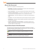
About this Document This document is divided into the following sections: • Introduction - This section is comprised of an overview of the Threat Analysis Reporter product and how to use this document • Service Information - This section provides 8e6 Technologies contact information • Preliminary Setup Procedures - This section includes instructions on how to physically set up the Threat Analysis Reporter unit in your network environment • Install the Server - This section explains how to configure t
Service Information The user should not attempt any maintenance or service on the unit beyond the procedures outlined in this document. Any initial hardware setup problem that cannot be resolved at your internal organization should be referred to an 8e6 Technologies solutions engineer or technical support representative. 8e6 Corporate Headquarters (USA) Local Domestic US International : : : 714.282.6111 1.888.786.7999 +1.714.282.
Preliminary Setup Procedures Unpack the Unit from the Carton Inspect the packaging container for evidence of mishandling during transit. If the packaging container is damaged, photograph it for reference. Carefully unpack the unit from the carton and verify that all accessories are included. Save all packing materials in the event that the unit needs to be returned to 8e6 Technologies.
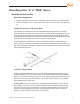
Rack Mount the “S” or “MSA” Server Rack Mount Instructions Rack Setup Suggestions • • Determine the placement of each component in the rack before you install the rails. Install the heaviest server components on the bottom of the rack first, and then work up. Identify the Sections of the Rack Rails You should have received two rack rail assemblies with the 8e6 server unit.
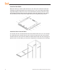
Install the Rack Rails Determine where you want to place the server unit in the rack. Position the fixed rack rail/sliding rail guide assemblies at the desired location in the rack, keeping the sliding rail guide facing the inside of the rack. Screw the assembly securely to the rack using the brackets provided. Attach the other assembly to the other side of the rack, making sure that both are at the exact same height and with the rail guides facing inward.
Installing the Server into a Telco Rack If you are installing the 8e6 server unit into a Telco type rack, follow the directions given on the previous pages for rack installation. The only difference in the installation procedure will be the positioning of the rack brackets to the rack. They should be spaced apart just enough to accommodate the width of the Telco rack.
Install the “H” Server Bezel Before rack mounting the “H” unit, the bezel should be installed on the front end of the chassis. This portion of the installation process requires you to unpack the unit and bezel. NOTE: The bezel has been packaged separately from the unit to prevent damage during shipping.
A. Remove the plastic wrapping from the left and right ears. B. On one side of the chassis (left or right), unscrew the inner rail from the chassis. C. Slide the loosened inner rail slightly backwards to release it from the clips at the side of the chassis, and then lay it down beside the chassis, with the inside of the rail facing up. D. On the inner rail that is still attached to the chassis, insert the bezel pin into the bottom hole of the ear.
F. Return the loosened inner rail to its upright position and insert the bezel pin into the bottom hole of the ear. G. Slide the inner rail forward beneath the clips to lock it in place. H. Screw the inner rail back on the chassis. I. 10 After it is installed, the bezel should drop down when it is gently tugged forward and downward. The bezel should remain upright when raised up and closed.
Rack Mount the “H” Server Rack Mount Instructions Identify the Sections of the Rack Rails You should have received two rack rail assemblies with the 8e6 server unit. Each of these assemblies consists of two sections: An inner fixed chassis rail that secures to the unit (A), and an outer fixed rack rail that secures directly to the rack itself (B). Two pairs of short brackets to be used on the front side of the outer rails are also included.
Install the Server into the Rack You should now have rails attached to both the chassis and the rack unit. The next step is to install the server chassis into the rack. Do this by lining up the rear of the chassis rails with the front of the rack rails. Slide the chassis rails into the rack rails, keeping the pressure even on both sides (you may have to depress the locking tabs when inserting). When the server has been pushed completely into the rack, you should hear the locking tabs “click.
Installing the Server into a Telco Rack If you are installing the 8e6 server unit into a Telco type rack, follow the directions given on the previous page for rack installation. The only difference in the installation procedure will be the positioning of the rack brackets to the rack. They should be spaced apart just enough to accommodate the width of the Telco rack.
Install the Server Step 1: Initial Setup Procedures This step requires you to link the workstation to the Threat Analysis Reporter.
Link the Workstation to the Threat Analysis Reporter Monitor and Keyboard Setup A. Connect the PC monitor and keyboard cables to the rear of the chassis. B. Turn on the PC monitor. C. Power on the Threat Analysis Reporter unit by dropping down the face plate and pressing the large button at the right of the front panel (see image below). Front of the chassis Once the Threat Analysis Reporter is powered up, proceed to the Step-by-Step Initial Setup Procedures. Serial Console Setup A.
HyperTerminal Setup Procedures If using a serial console, follow these procedures to create a HyperTerminal session. A. Launch HyperTerminal by going to Start > Programs > Accessories > Communications > HyperTerminal: B.
C. At the Connect using field, select the COM port assigned to the serial port on the laptop (probably “COM1”), and then click OK to open the Properties dialog box, displaying the Port Settings tab: D. Specify the following session settings: • • • • • Bits per second: 9600 Data bits: 8 Parity: None Stop bits: 1 Flow control: Hardware E.
F. In the HyperTerminal session window, go to File > Properties to open the Properties dialog box, displaying the Connect To and Settings tabs: G. Click the Settings tab, and at the Emulation menu select “VT100”. H. Click OK to close the dialog box, and to go to the login screen. NOTE: If using a HyperTerminal session, the login screen will display with black text on a white background.
Step-by-Step Initial Setup Procedures For these step-by-step procedures, you will need your network administrator to provide you the LAN 1 (Ethernet 0) and LAN 2 (Ethernet 1) IP address and subnet mask, gateway IP address, DNS server IP address(es), host name of the server, and IP address for the Web interface (if using a NAT device).
E. At the Press the number of your selection prompt, press 2 to display the Administrator Password Entry screen: F. At the Enter the administrator password prompt, re-enter your password: #s3tup#r3k G. Press Enter to display the Administration menu where you can begin the step-bystep initial setup process using the configuration screens: H. At the Press the number of your selection prompt, press 2 to select the “Initial Setup step-by-step” process.
Configure Network Interface screen A. At the Enter interface LAN1 (eth0) IP address field, enter the IP address for the LAN 1 (Ethernet 0) interface, and then press Enter to go to the next screen. B. At the Enter interface LAN1 (eth0) netmask field, enter the subnet mask for the LAN 1 (Ethernet 0) interface using the dotted decimals notation format. Press Enter to display the confirmation prompt.
C. Press Y for “Yes” to confirm and save your entries for the LAN1 (eth0) interface, and to go to the next screen. D. At the Enter interface LAN2 (eth1) IP address field, enter the IP address for the LAN 2 (Ethernet 1) interface, and then press Enter to go to the next screen. E. At the Enter interface LAN2 (eth1) netmask field, using the dotted decimals notation format, enter the subnet mask for the LAN 2 (Ethernet 1) interface. Press Enter to display the confirmation prompt. F.
Configure default gateway screen A. At the Enter default gateway IP field, enter the IP address for the default gateway. Press Enter to display the confirmation prompt. B. Press Y for “Yes” to confirm and save your entry for the gateway IP address, and to go to the Configure Domain Name Servers screen.
A. At the Enter first DNS server IP field, enter the IP address for the primary Domain Name Server. Press Enter to go to the next screen. B. At the Enter (optional) second DNS server IP field, if you have a secondary Domain Name Server you wish to use, enter the IP address for that server. Press Enter to display the confirmation prompt. C. Press Y for “Yes” to confirm and save your entries for the domain name servers, and to go to the Configure Host Name screen.
A. At the Enter host name field, enter the host name of the server. Press Enter to display the confirmation prompt. B. Press Y for “Yes” to confirm and save your entry for the host name, and to go to the Time zone regional configuration screen. Time zone regional configuration screen A. Use the up and down arrows in your keyboard to select your region.
B. Use the up and down arrows in your keyboard to select your region. After selecting your locality, press Y for “Yes” to confirm and save your regional selection, and to go to the Configure Wizard user screen. Configure Wizard user screen A. At the Enter wizard user name field, enter the username that will be used to access the setup wizard in the Threat Analysis Reporter interface. Press Enter to display the confirmation prompt. B.
C. At the Enter wizard password field, enter the password that will be used to access the setup wizard in the Threat Analysis Reporter interface. Press Y for “Yes” to confirm and save your entry and to go to the Setup Wizard Confirmation screen. Setup Wizard Confirmation screen Press Y for “Yes” to save all your wizard entries and to return to the Administration menu. NOTE: When saving your entries, there may be a 4-10 second delay before the Administration menu displays.
System Status Screen The System Status screen contains the following information: • • • • • • • LAN1 (eth0) interface for web access and R3000 communications: LAN1 (eth0) IP address and netmask specified in screen 3 (Configure Network Interface), and current status (“Active” or “Inactive”) LAN2 (eth1) interface for bandwidth monitoring: LAN2 (eth1) IP address and netmask specified in screen 4 (Configure Network Interface), and current status (“Active” or “Inactive”) Default gateway IP address specified in
Step 2: Physically Connect the Unit to the Network After performing initial setup procedures for the Threat Analysis Reporter, the unit should be physically connected to the network. This step requires a standard CAT-5E cable to connect the unit to the network. An additional CAT-5E cable is required if the Ethernet Tap unit will be installed for bandwidth monitoring. A. Plug one end of a standard CAT-5E cable into the Threat Analysis Reporter’s LAN 1 port, the port on the left.
Step 3: Wizard Setup Procedures For this step, you will need your network administrator to provide you the following information: • • • IP range and netmask of machines on the network the Threat Analysis Reporter server will be monitoring R3000 IP address, port number to be used between the R3000 and Threat Analysis Reporter, and type of authentication method to be used (IP group or LDAP) 8e6 Enterprise Reporter server IP address and server name, if an ER unit is connected to the R3000 Access the Threat A
D. After reading the End User License Agreement, you have the option to do either of the following: • Click No to close both the EULA Agreement dialog box and the Threat Analysis Reporter interface. You will not be able to enable the Threat Analysis Reporter for use in your environment. • Click Yes to close the EULA Agreement dialog box and to open the Login dialog box: Proceed to the next sub-section: Log in to the Threat Analysis Reporter Administrator Console.
Step 1: Register administrator Step 1 is performed in the left side of the first screen of the wizard: A. Enter the username the global administrator will use when logging into the Threat Analysis Reporter Administrator console. The global administrator has the highest level of permissions in the Threat Analysis Reporter interface. B. Enter the password to be used with that username, and enter the same password again in the confirm password field. C.
D. Click the [+] Add tab beow to open the IP Range Information dialog box: E. Enter the IP address range for the bandwidth the Threat Analysis Reporter will monitor. F. Enter the Netmask for the IP range to be monitored, using the dotted decimals notation format. G.
NOTE: Additional IP address ranges can be included by clicking the [+] Add tab again and making the entries described in steps E through G above. To modify an IP address range, double-click the entry in the list box to highlight it and to display the [-] Remove tab to the left of the [+] Add tab: 34 • To modify the entries made for the IP address range, click the [+] Add tab to reopen the IP Range Information dialog box and edit information, as necessary.
Step 2: Register R3000 & ER Step 2 is performed in the right side of the first screen of the wizard. R3000: Specify information for the R3000 to be used with the Threat Analysis Reporter: A. Click the [+] Add tab above the R3000 list box to open the R3000 Information dialog box: B. Enter the IP address of the R3000 server to be used with the Threat Analysis Reporter. In our example, this is: 200.100.160.74, which is the Ethernet 1 IP address of the R3000 server. C.
E. Click OK to close the dialog box and to display your entries in the list box: NOTE: Additional R3000 servers can be included by clicking the [+] Add tab again and making the entries described in steps A through E above.
• To modify the IP address and Server Name for the R3000 server, click the [+] Add tab to re-open the R3000 Information dialog box, and edit information as necessary. Click OK to close the dialog box and to display the modified information in the list box. • To designate an R3000 as the Master R3000 server, click the entry for the R3000 server in the list box to highlight it, and then click the Set as Master tab to display “Master” in the Master column for that entry in the list box.
NOTE: To change your answer from “Yes” to “No,” click the < Back button to re-display the question “Do you have an Enterprise Reporter?” A. Enter the IP address of the ER server to be used with the Threat Analysis Reporter. In our example, this is: 200.10.101.76. B. Enter the Server Name of the ER server to be used with the Threat Analysis Reporter. In our example, this is: er4logo. C. Click NEXT > at the bottom right of the screen to go to Step 3.
Step 3: Register Gauges Step 3 requires you to specify settings for default gauges to be monitored by the Threat Analysis Reporter. These gauges will display in the Threat Analysis Reporter interface upon logging into the Administrator console. NOTE: Return to Step 1 or Step 2 by clicking the < BACK button in the lower left corner of this wizard screen.
View, Edit Gauge Components To view gauge components for a specified gauge, highlight and double-click the gauge name to populate the the fields to the right of the Gauge Groups list box. The following gauge criteria can be edited: • Name: The displayed gauge name to be used in the interface can be modified by making an entry in this field.
Step 4: Server Settings In Step 4, the following R3000 server information displays: Active Directory Settings, SMTP Server Settings, Patch Server Settings, PROXY Server Settings, NTP Server Settings: NOTE: Return to Step 3 by clicking the < BACK button in the lower left corner of this wizard screen. After reviewing the information in this screen, the following actions can now be performed: • To print this information, click the Print button.
Conclusion Congratulations; you have completed the Threat Analysis Reporter quick start procedures. Now that the Threat Analysis Reporter is running on your network, the next step is to set up user groups or administrator groups. You will set up and configure gauges thereafter. Obtain the latest Threat Analysis Reporter User Guide from our Web site at http:// www.8e6.com/docs/tar_ug.pdf.
Specifications Physical Specifications Specification “S” Value “H” Value “MSA” Value Height Width Depth Front clearance Side clearance Rear clearance Weight 1.7” (43mm) 16.8” (426mm) 22.6” (574mm) 2 inches (76mm) 1 inch (25mm) 3.6 inches (92mm) 19.5 lbs (8.85 kg) 1.7” (43mm) 17.2” (438mm) 26.8” (681mm) 2 inches (76mm) 1 inch (25mm) 3.6 inches (92mm) 43.0 lbs (19.5 kg) 1.7” (43mm) 16.8” (426mm) 14.0” (356mm) 2 inches (76mm) 1 inch (25mm) 3.6 inches (92mm) 11 lbs, 5 oz (5.
Hardware Component Specifications iv Specification “S” Value “H” Value “MSA” Value Operating temperature range 10° C ~ 35° C (50° F ~ 95° F) 10° C ~ 35° C (50° F ~ 95° F) 10° C ~ 35° C (50° F ~ 95° F) Storage temperature range -40° C ~ +60° C (40° F ~ 158° F) -40° C ~ +60° C (40° F ~ 158° F) -40° C ~ +70° C (40° F ~ 158° F) Operating humidity range 8 ~ 90% non-condensing 8 ~ 90% non-condensing 8 ~ 90% non-condensing Storage humidity range 5 ~ 95% non-condensing 5 ~ 95% non-condensing 5
“S” and “MSA” Front Panel LED Indicators, Buttons Diagrams and Descriptions On “S” and “MSA” units, LED indicators and buttons display on the front panel to the right: E D C B F A G LED indicators alert you to the status of a feature on the unit while buttons let you perform a function on the unit. LED Indicators and Buttons LED Indicator Key Button Key A. Power F. Reset B. HDD Activity G. Power C. LAN 1 D. LAN 2 E.
Tap Installation Appendix: Optional Ethernet Tap Installation This appendix pertains to the optional installation of the Ethernet Tap unit for bandwidth monitoring. Preliminary Setup Procedures Unpack the Ethernet Tap Unit from the Box Open the NetOptics Ethernet Tap box and verify that all accessories are included. Save all packing materials in the event that the unit needs to be returned to 8e6 Technologies.
Tap Installation Install the Ethernet Tap Unit Diagram showing TAR Ethernet Tap installation on the network This step is a continuation from Step 2: Physically Connect the Unit to the Network. The procedures outlined in this step require the use of a CAT-5E cable. A. Provide power to the Ethernet Tap by connecting both power cords from the unit to the power source. AC power in rear panel of NetOptics 10/100BaseT Tap B.
Tap Installation C. Using a crossover cable, connect one end to the Switch’s port configured to be the destination port of the Port Mirror. If adding a Threat Analysis Reporter to an existing installation, this port would be the port that was originally occupied by the listening interface of the R3000. D. Connect the other end of the crossover cable to the Ethernet Tap’s Network A port. Ports in front panel of NetOptics 10/100BaseT Tap E.
Tap Installation 8e6 Threat Analysis Reporter Quick Start Guide 49
8e6 Corporate Headquarters (USA): 828 West Taft Avenue Orange, CA 92865-4232 • Tel: 714.282.6111 or 888.786.7999 Fax: 714.282.6116 (Sales/Technical Support) • 714.282.6117 (General Office) Satellite Office: 8e6 Taiwan: RM B2, 13F, No. 49, Sec. 3, Minsheng E. Rd., Taipei 104, Taiwan, R.O.C.