® R3000 | Internet Filter QUICK START GUIDE Model: R3000IR MSA-002-003 R3000 Release: 2.1.10, ER Release: 4.1.20 / Updated: 12.01.
8e6 Internet Filter with Integrated Reporter Quick Start Guide © 2008 8e6 Technologies. All rights reserved. This document may not, in whole or in part, be copied, photocopied, reproduced, translated, or reduced to any electronic medium or machine readable form without prior written consent from 8e6 Technologies. Every effort has been made to ensure the accuracy of this document.
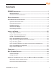
Contents R3000IR Introduction...............................................................................1 About this Document..................................................................................................................... 2 Conventions Used in this Document............................................................................................ 3 Service Information...................................................................................4 Preliminary Setup Procedures..
LED Indicators and Buttons...................................................................73 Diagrams and Descriptions......................................................................................................... 73 Regulatory Specifications and Disclaimers.............................................74 Declaration of the Manufacturer or Importer............................................................................. 74 Index..............................................................
R3000IR Introduction Thank you for choosing to evaluate the 8e6 Technologies R3000IR Internet Filter with Integrated Reporter. This product combines the R3000 Internet Filter with the ER Enterprise Reporter to track end user Internet activity and generate reports that assist administrators in developing policies and targeting sites to be filtered, in order to maximize bandwidth utilization and productivity.
About this Document This document is divided into the following sections: • Introduction - This section is comprised of an overview of the R3000IR product and how to use this document • Service Information - This section provides 8e6 Technologies contact information • Preliminary Setup Procedures - This section includes instructions on how to physically set up the R3000IR in your network environment • Install the Server - This section explains how to configure the R3000IR for filtering and report
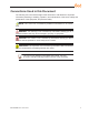
Conventions Used in this Document The following icons are used throughout this document to call attention to important information pertaining to handling, operation, and maintenance of the server; safety and preservation of the equipment, and personal safety: NOTE: The “note” icon is followed by additional information to be considered. WARNING: The “warning” icon is followed by information alerting you to a potential situation that may cause damage to property or equipment.
Service Information The user should not attempt any maintenance or service on the unit beyond the procedures outlined in this document. Any initial hardware setup problem that cannot be resolved at your internal organization should be referred to an 8e6 Technologies solutions engineer or technical support representative. 8e6 Corporate Headquarters (USA) Local Domestic US International : : : 714.282.6111 1.888.786.7999 +1.714.282.
Preliminary Setup Procedures Unpack the Unit from the Carton Inspect the packaging container for evidence of mishandling during transit. If the packaging container is damaged, photograph it for reference. Carefully unpack the unit from the carton and verify that all accessories are included. Save all packing materials in the event that the unit needs to be returned to 8e6 Technologies.
Select a Site for the Server The server operates reliably within normal office environmental limits. Select a site that meets the following criteria: • Clean and relatively free of excess dust. • Well-ventilated and away from sources of heat, with the ventilating openings on the server kept free of obstructions. • Away from sources of vibration or physical shock.
Rack Mount the Server Rack Setup Precautions Warning: Before rack mounting the server, the physical environment should be set up to safely accommodate the server. Be sure that: • The weight of all units in the rack is evenly distributed. Mounting of the equipment in the rack should be such that a hazardous condition is not achieved due to uneven mechanical loading. • The rack will not tip over when the server is mounted, even when the unit is fully extended from the rack.
Rack Mount Instructions Optional: Install the Chassis Rails NOTE: If your chassis does not come with chassis rails, please follow the procedure listed on the last page of this sub-section to install the unit directly into the rack. CAUTION: Please make sure that the chassis covers and chassis rails are installed on the chassis before you install the chassis into the rack.
3. Locate the three holes on each side of the chassis and locate the three corresponding holes on each of the inner rail. 4. Attach an inner rail to each side of the chassis and secure the inner rail to the chassis by inserting three Type G screws through the holes on each side of the chassis and the inner rail. (See the diagram below for a description of the Type G screw.) 5. Repeat the above steps to install the other rail on the chassis.
Optional: Install the Traditional UP Racks After you have installed the inner rails on the chassis, you are ready to install the outer rails of rail assemblies to the rack. NOTE: The rails are designed to fit in the racks with the depth of 28” to 33”. • • Determine the placement of each component in the rack before you install the rails. Install the heaviest server components on the bottom of the rack first, and then work up. 1. In the package, locate a pair of front (short) and rear (long) brackets.
7. Slide the chassis into the rack as shown below. NOTE: The chassis may not slide into the rack smoothly or easily when installed the first time. Some adjustment to the slide assemblies might be needed for easy installation. 8. You will need to release the safety taps on both sides of the chassis in order to completely remove the chassis out of the rack.
Optional: Install the Open Racks After you have installed the inner rails on the chassis, you are ready to install the outer rails of rail assemblies to the rack. NOTE: The rails are designed to fit in the racks with the depth of 28” to 33”. • • Determine the placement of each component in the rack before you install the rails. Install the heaviest server components on the bottom of the rack first, and then work up. 1. In the package, locate a pair of front (short) and rear (long) brackets.
3. Attach the front (short) bracket to the front end of the rack, and secure it to the rack with two Type H screws and Type I washers as shown below. (See the previous page for descriptions of Type H and Type I hardware components.) 4. Attach the rear (long) bracket to the rear end of the rack, and secure it to the rack with two Type H screws and Type I washers as shown below. Repeat the same steps to install the other outer rail to the other side of rack.
5. Measure the depth of your rack and adjust the length of the rails accordingly. Then, secure the rails to the chassis with Type G screws. 6. Slide the inner rails which are attached to the chassis into the outer rails on the rack.
Install the Chassis into the Rack CAUTION: Before installing the chassis into the rack: • • • • • • Make sure that the rack is securely anchored onto an unmovable surface or structure before installing the chassis into the rack. Unplug power cord(s) of the rack before installing the chassis into the rack. Make sure that the system is adequately supported. Make sure that all the components are securely fastened to the chassis to prevent components falling off from the chassis.
Check the Power Supply This server is equipped with a universal power supply that handles 100-240 V, 50/60 Hz. A standard power cord interface (IEC 950) facilitates power plugs that are suitable for most European, North American, and Pacific Rim countries. Power Supply Precautions Warning: 16 • Use a regulating uninterruptible power supply (UPS) to protect the server from power surges, voltage spikes and to keep the server operating in case of a power failure.
General Safety Information Server Operation and Maintenance Precautions Warning: Observe the following safety precautions during server operation and maintenance: WARNING: If the server is used in a manner not specified by the manufacturer, the protection provided by the server may be impaired. WARNING: 8e6 Technologies is not responsible for regulatory compliance of any server that has been modified.
AC Power Cord and Cable Precautions Warning: • The AC power cord for the server must be plugged into a grounded, power outlet. • Do not modify or use a supplied AC power cord if it is not the exact type required in the region where the server will be installed and used. Replace the cord with the correct type. • Route the AC power cord and cables away from moving parts and foot traffic. • Do not allow anything to rest on the AC power cord and cables.
Motherboard Battery Precautions Caution: The battery on the motherboard should not be replaced without following instructions provided by the manufacturer. Only qualified service personnel should replace batteries. The battery contains energy and, as with all batteries, a malfunction can cause heat, smoke, or fire, release toxic materials, or cause burns. Do not disassemble, puncture, drop, crush, bend, deform, submerge or modify the battery. Do not incinerate or expose to heat above 140°F (60°C).
Install the Server Step 1: Setup Procedures This step requires you to link the workstation to the R3000IR. You have the option of using the text-based Quick Start setup procedures described in Step 1A, or the Administrator console setup procedures described in Step 1B.
Step 1A: Quick Start Setup Procedures Link the Workstation to the R3000IR Monitor and Keyboard Setup A. Connect the PC monitor and keyboard cables to the rear of the chassis (see Fig. 1). B. Turn on the PC monitor. C. Power on the R3000IR by dropping down the face plate and pressing the large button at the right of the front panel (see Fig. 2). Once the R3000IR is powered up, proceed to the Login screen instructions. Serial Console Setup A.
HyperTerminal Setup Procedures If using a serial console, follow these procedures to create a HyperTerminal session. A. Launch HyperTerminal by going to Start > Programs > Accessories > Communications > HyperTerminal: B. In the Connection Description dialog box, enter any session Name, and then click OK to open the Connect To dialog box: C.
D. Specify the following session settings: • • • • • Bits per second: 9600 Data bits: 8 Parity: None Stop bits: 1 Flow control: Hardware E.
F. In the HyperTerminal session window, go to File > Properties to open the Properties dialog box, displaying the Connect To and Settings tabs: G. Click the Settings tab, and at the Emulation menu select “VT100”. H. Click OK to close the dialog box, and to go to the login screen. NOTE: If using a HyperTerminal session, the login screen will display with black text on a white background.
Login screen The login screen displays after powering on the R3000IR unit using a monitor and keyboard, or after creating a HyperTerminal session. NOTE: If the screensaver currently displays on your screen, press the Enter key to display the login screen. A. At the login prompt, type in menu. B. Press the Enter key to display the Password prompt. C. At the Password prompt, type in the following: #s3tup#r3k D. Press Enter to display the Quick Start menu screen. Quick Start menu screen A.
Quick Start menu: administration menu A. At the Press the number of your selection prompt, press 2 to select the “Quick Start Setup” process.
NOTES: Changing your password using option C, “Change Quick Start password”, will change the password for the console menu but not the R3000 console login screen. Option A, “Reset system to factory defaults”, should only be used by an 8e6 Technologies technical representative. Option D, “Reset admin console account”, should be used for resetting the administrator console username and password to the factory default ‘admin’/’user3’ and for unlocking all IP addresses currently locked.
NOTE: Modifications can be made at any time by returning to the specific screen of the Quick Start procedures. Log Off, Disconnect the Peripherals A. After completing the Quick Start setup procedures, return to the Quick Start menu screen and press 9 to log out. B. Disconnect the peripherals from the R3000IR.
Step 1B: Console Setup Procedures Preliminary Setup Create a “setup workstation” using a Windows-based laptop or desktop machine with a network card and Internet Explorer 5.5 (or later). The setup workstation will be used for accessing the R3000 Administrator console on the network and configuring the server. NOTE: The Java Plug-in version specified for the R3000 software version must be installed on your workstation.
Link the Workstation to the R3000IR The procedures outlined in this sub-section require the use of the CAT-5E crossover cable. A. Plug one end of the CAT-5E crossover cable into the R3000IR’s LAN 2 port. NOTE: When facing the rear of the chassis, the LAN 2 port is the port on the right. Portion of MSA chassis rear B. Plug the other end of the CAT-5E crossover cable into the setup workstation’s network card.
The Boot Up Process The boot-up process may take 5 - 10 minutes. When the drive light remains off for 30 seconds, the system is booted up. (See the LED Indicators and Buttons section for a description of front panel LED indicators and buttons.) If you wish to verify that the unit has been booted up, you can perform the following test on your workstation: 1. 2. 3. 4. 5. Go to your taskbar and click Start > Run. In the dialog box, type in cmd (type in command if using Windows ME). Click OK. In the cmd.
Log in to R3000 Administrator Console A. In the console, click the link for Filtering to open the R3000 Introductory Window: NOTE: This window must be left open throughout your session. The Introductory Window displays minimized when the login dialog box of the R3000 Administrator console application opens: B. In the Username field, type in admin. C. In the Password field, type in user3.
D.
Network Click the System button at the top of the screen to go to the System section of the console: In this section of the console you will: • • • • Specify the operation mode the R3000 will use for filtering the network, listening to traffic, and sending traffic Configure LAN settings the R3000 will use on your network Select NTP servers the R3000 will use for time synchronization with Internet clocks Indicate the region in which the R3000 is geographically located NOTE: After saving your entries in ea
Network: Operation Mode From the navigation panel at the left of the screen, click Mode and choose Operation Mode from the pop-up menu: Make the following entries in the Operation Mode window: A. In the Mode frame, select the operational mode the R3000 will use for filtering: Invisible, Router, Firewall, Mobile, or ICAP. NOTE: Refer to the appendix in the R3000 User Guide for information on configuring the R3000 to use the Mobile mode option with the 8e6 Mobile Client. B.
D. Click Apply. Network: LAN Settings From the navigation panel, click Network and choose LAN Settings from the pop-up menu: Make the following entries for the R3000 in the LAN Settings window: A. Enter the Host Name that includes your domain name, for example R3000SERVER. myserver.com (the NetBIOS name must be capitalized). It is important to enter something identifiable, because once the product is registered, this host name is used by 8e6 Technologies to recognize your account for library updates.
WARNING: For the router and firewall mode, do not use the same subnet for LAN 1 and LAN 2 or the console will become inaccessible. D. Enter the Primary IP address of the first DNS name server. The R3000 uses this name server to resolve the domain name requested by users from the LAN. E. Enter the Secondary IP address of the second DNS name server. The R3000 will use this name server to resolve the domain name requested by users from the LAN if the first DNS isn’t working. F.
The NTP Servers window is used for specifying the Network Time Protocol (NTP) servers to be used by the R3000, so that the R3000 is synchronized with computer clocks on the Internet. Note that the following server IP addresses display in the Servers list box: 128.59.35.142, 142.3.100.15, 129.132.98.11. If necessary, any of these servers can be deleted by selecting the IP address and clicking Delete.
Network: Regional Setting From the navigation panel, click Network and choose Regional Setting from the pop-up menu: Make the following selections in the Regional Setting window: A. At the Region pull-down menu, select your country from the available choices. B. At the Location pull-down menu, select the time zone for the specified region. If necessary, select a language set from the Language pull-down menu to display that text in the console. C. Click Apply to apply your settings, and to reboot the R3000.
Physically Connect the R3000IR to the Network Once your R3000 network parameters are set, you must physically connect the unit to your network. This step requires two standard CAT-5E cables. NOTE: This section requires you to restart the R3000. If you wish to relocate the R3000IR before connecting it to the network, you must first shut down the server instead of restarting it. To shut down the R3000, go to the navigation panel, click Control, and then select ShutDown.
Step 2: Test the R3000 Console Connection Now that the R3000IR is physically installed on your network and you have configured its network settings, you need to test the unit to see if it is set up properly. A. Restore the setup workstation you used for the Network Setup to its original settings, and connect it to the network hub to create a “network workstation.” (You could also use another workstation already on the network that has Internet access.) B.
Step 3: Test Filtering or Mobile Client Console Connection Test Filtering If this R3000 has been set up in the Invisible, Router, or Firewall mode, once you have accessed the R3000 Administrator console, you should test filtering. A. Test the R3000’s filtering by opening a browser window on a network workstation, and going to http://test.8e6.net (an empty site for testing pornography filtering). B. You should receive a block page.
Step 4: Set Library Updates After verifying that the R3000 is correctly installed on your network, you need to activate R3000 library updates. Library updates are critical for filtering as new sites are added to the 8e6 library each day. To activate updates, visit the 8e6 Technologies Web site and enter the activation code that was issued to you by e-mail (also included on the product invoice). NOTE: Port 443 (HTTPS) must be open for outgoing requests so that the R3000 can receive library updates.
Perform a Complete Library Update Your R3000IR was shipped with the latest library update for the current software release. However, as new updates continually become available, before you begin using the R3000IR you must perform a complete library update to ensure you have the latest library updates. To download the latest library updates, go to the R3000 Administrator console. A. Click the Library button at the top of the screen. B.
Monitor the Library Update Process To verify that the library is being updated: A. From the navigation panel, click Updates and select Library Update Log from the menu. B. In the Library Update Log window, click View Log to display the update activity: NOTE: You will be notified in the log when the library has been completely updated by the message: “Full URL Library Update has completed.” If this message does not yet display, click View Log again to view the latest information.
Now that the R3000 is filtering your network, the next step is to set up groups and create filtering profiles for group members. To activate a default filter profile more appropriate for your operations, or to specify a more limited IP range to filter, consult Chapter 2: Group screen in the Global Administrator Section of the R3000 User Guide. Refer to Chapter 1: System screen for information on how to give end users access to acceptable HTTPS sites if strict HTTPS filtering settings are used.
Step 5: Change the ER Admin User Name and Password, Set Self-Monitoring After configuring the R3000, click the Quit button at the top of the screen to exit the R3000 Administrator console. You will now need to log in to the ER Administrator console and make some changes to settings in screens. Log in to the ER Administrator Console A. In the R3000IR console (see Step 1B: Network Setup, Access the R3000IR Administrator Console), click the link for Reporting to open the ER Administrator console: B.
D. Click OK to go to the main screen of the ER Administrator console: Change User Name and Password A. Set up a new administrator user name and password by clicking on the Network pulldown menu and choosing Administrators to display the Add/Edit/Delete Administrators screen: B. Select New Administrators from the pull-down menu.
C. Enter a User Name and Password. D. In the Confirm Password field, re-enter the password. E. Click Save. Set Self-Monitoring A. From the Server pull-down menu, choose Self-Monitoring to display the Self Monitoring screen: B. Choose YES to activate monitoring. C. Enter the Master Administrator’s E-Mail Address. D. Click Choice one and enter an e-mail address of an individual in your organization that you would like notified if the ER detects any problems when processing data.
Step 6: Client Workstation Configuration Once your ER is installed, you need to be sure the workstation that will run the client has the following minimum requirements: • • • • • • • • Pentium III class processor or greater 512 MB RAM minimum, 1 GB RAM recommended 1,024 x 768 display 2 GB free hard drive space Windows 2000 or XP, or Macintosh OS X operating system Internet Explorer Version 6.0 or later, Firefox 1.5, or Safari 2.
Step 7: Launch the ER Client A. Launch IE, enter http://x.x.x.x:8080 or https://x.x.x.x:8443 in the address window (in which “x.x.x.x” represents the IP address of the ER server), and then click Go to access the login window of the ER client. B. Enter your Username and Password, and then click LOGIN to access the main screen of the client: NOTE: If you do not have your own Username and Password set up in the ER client, the default Username is manager and the default Password is 8e6ReporT.
C. In the navigation panel, select Settings, and then choose User Permissions from the menu: D. Click Add User to open the Enter User Permissions dialog box: E. Enter the Username. F. Enter the Password, and Confirm Password. G. Select the User Type (“Admin” or “Sub-Admin”). H. Click Save to close the dialog box, and to add the username to the user list. I. Exit the client. You can now launch the client and enter the password you just set up.
Conclusion Congratulations; you have completed the R3000IR quick start procedures. Now that the R3000 and ER are set up on your network, once the ER database is populated with logs from the R3000, the client can be used for generating reports. Initially, you will only be able to report on IP addresses. To implement user names in ER reporting, please consult the ER Administrator User Guide. Refer to the ER Web Client User Guide for information on generating reports.
Best Filtering Practices Threat Class Groups 8e6’s filtering library currently consists of 103 library filtering categories, each placed in one of the 20 filtering category groups defined in the interface: Adult Content, Bandwidth, Business/Investments, Community/Organizations, Education, Entertainment, Government/Law/Politics, Health/Fitness, Illegal/Questionable, Information Technology, Internet Communication, Internet Productivity, Internet/Intranet Misc.
Filtering Scenarios This collection of filtering scenarios is designed to help you get started filtering the network. Each scenario is followed by R3000 setup information. Please consult the “How to” section in the index of the R3000 User Guide for pages containing detailed, step-by-step instructions on configuring and/or using the tools and features in that scenario. I. Threats/Liabilities 1. Category block Block categories that threaten your network/organization.
To block categories in a profile using the X Strikes Blocking feature, go to: • SYSTEM: System > X Strikes Blocking > Configuration tab, and Categories tab • GROUP: Group > IP > member > member Profile > Filter Options tab, X Strikes Blocking enabled or GROUP: Group > Global Group > Global Group Profile > Filter Options tab (X Strikes Blocking enabled) In the R3000 User Guide index, see: • How to: set up X Strikes Blocking • How to: set up profile options 4.
6. Search Engine Keywords Block access to network-endangering content via search engine keywords. In pertinent library categories, enter SE keywords to be blocked. Block these categories in applicable profiles.
9. Override Account bypass Use an Override Account to grant a user access to categories blocked at the root level. To grant designated users access to globally-blocked categories, set up an Override Account at the Global Group level, or enable the option to allow the Minimum Filtering Level to be bypassed with an Override Account, and then set up the Override Account at the group level.
In the R3000 User Guide index, see: • How to: configure filtering • How to: use library categories in a profile 12. File type blocking Prevent users from downloading and using executable files that may threaten your network security. Create a custom category for file extensions and add “.exe” to the URL Keyword list. Other files you might include in the list are: .dll, .ocx, .scr, .bat, .pif, .cpl, .cmd, .hta, .lnk, .inf, .sys, .vbs, .vb, .wsc, .wsh, .wsf. Do NOT include “.
2. Overall Quota Restrict all quota time in a profile to improve bandwidth usage and productivity. Cap the amount of time a user spends in all quota-marked categories by enabling the Overall Quota option and specifying the number of minutes the end user can visit quota-marked categories before being notified and then locked out of these categories.
In the R3000 User Guide index, see: • How to: configure filtering • How to: configure the Warn Option Setting • How to: use library categories in a profile 5. Warn-strike Warn users before they access unacceptable content and may be locked out of the Internet. Enable the Warn feature along with X Strikes Blocking. After the end user is warned for the designated number of times defined in X Strikes Blocking, that user is locked out of all Internet/intranet access.
7. IM patterns Block IM services. Enable Pattern Blocking for all users. In the profile, block Internet Communication > Chat and Instant Messaging (IM) categories. To block IM services, go to: • SYSTEM: System > Control > Filter window • GROUP: Group > IP > member > member profile > Category tab or GROUP: Group > Global Group > Global Group Profile > Category tab In the R3000 User Guide index, see: • How to: configure filtering • How to: use library categories in a profile 8.
10. Remote Access patterns Block remote access patterns. Enable Pattern Blocking for all users. In the profile, block Internet Productivity > Remote Access category. To block remote access patterns, go to: • SYSTEM: System > Control > Filter window • GROUP: Group > IP > member > member profile > Category tab or GROUP: Group > Global Group > Global Group Profile > Category tab In the R3000 User Guide index, see: • How to: configure filtering • How to: use library categories in a profile 11.
13. Rule block Use a rule to block the Bandwidth category. Create a rule that blocks the Bandwidth category and apply this rule to pertinent profiles. To create and block a rule for the Bandwidth category, go to: • GROUP: Group > Global Group > Rules • Group > IP > member > member profile > Category tab or Group > Global Group > Global Group Profile > Category tab In the R3000 User Guide index, see: • How to: use rules • How to: use library categories in a profile 14.
In the R3000 User Guide index, see: • How to: set up URL Keywords • How to: set up profile options 16. Custom Block/Warn/X Strikes/Quota pages Customize a block, warning, X Strikes, or quota pages. Modify page contents to point to a URL within your organization, send a request to your administrator’s email address, or include verbiage of your choice that informs users of their Internet usage activities that triggered the page.
III. General/Productivity 1. Warn Feature with higher thresholds Warn users before they access unacceptable content. Set HTTPS filtering at the “high” level to block certificates that may be questionable. Configure Warning settings. In the end user’s profile, apply the warn option to pertinent categories. The end user may not be able to access all requested sites due to high settings, and will receive the warning message for excessive Internet usage.
3. Time Quota/Hit Quota Limit time spent in PASSED categories to increase productivity. Enable the Quota Settings feature, and configure the Seconds Per Hit. Set up pertinent categories in the user’s profile with quotas so the user is notified and then locked out of those categories after all minutes in the quota have been used.
6. Customize an 8e6 Supplied Category Include region-specific content in an 8e6 Supplied category. Add/delete content to/from an existing 8e6 Supplied Category that only includes content pertinent to your organization or region that should be blocked. Apply this category to a profile.
IV. Pass/Allow 1. Always Allow Custom Category Create a white list custom category. Set up an Always Allow category and add all URLs deemed acceptable. Apply this category to all pertinent profiles.
4. Override Accounts Set up override accounts to grant specified users access to URLs blocked for general users. Enable the option to bypass the Minimum Filtering Level using an override account. Create the override account profile, including the accessible categories.
Important Information about using the ER in the Evaluation Mode When evaluating the ER and using this product in the evaluation mode, the Expiration screen in the Administrator console and the ER Server Statistics window in the client will display and function differently than they do in the activated (standard) mode of the ER (described in the ER Administrator User Guide and ER Web Client User Guide).
ER Client, ER Server Statistics Window In the ER Server Statistics window, the note “*Evaluation Mode Enabled” displays above the ER Activity frame. To the right of this note, the Info button displays. When this button is clicked, an alert box opens with the message: “Evaluation Mode – Max Data Storage ‘X’ Weeks” (in which ‘X’ represents the maximum number of weeks in the ER’s data storage scope). Click OK to close the alert box.
LED Indicators and Buttons Diagrams and Descriptions LED indicators and buttons for hardware status monitoring display on the front panel, located on the right side of the chassis (see diagram below). LED Indicator Key Button Key A = Power F = Reset B = HDD Activity G = Power C = LAN 1 Chassis control panel D = LAN 2 E = Overheat LED indicators alert you to the status of a feature on the unit while buttons let you perform a function on the unit.
Regulatory Specifications and Disclaimers Declaration of the Manufacturer or Importer Safety Compliance USA: UL 60950-1 2nd ed.
Electromagnetic Compatibility Class A Notice Industry Canada Equipment Standard for Digital Equipment (ICES-003) Bureau of Standards Metrology and Inspection (BSMI) - Taiwan 8e6 R3000IR Quick Start Guide 75
EC Declaration of Conformity European Community Directives Requirement (CE) Declaration of Conformity Manufacturer’s Name: 8e6 Technologies Manufacturer’s Address: 828 W.
Index A Always Allow Custom Category 69 B Bandwidth/Productivity 59 boot up 31 BSMI 74, 75 C Category block 55, 63 Change Quick Start password 27 Change User Name and Password 48 crossover cable 20, 30, 40 Custom Block/Warn/X Strikes/Quota pages 65, 68 Custom Category (blocked) 57 Customize an 8e6 Supplied Category 68 Custom Lock, Block, Warn, X Strikes, Quota pages 56 E EMC 74, 76 ER Client 51, 72 ER Server Statistics 71, 72 Evaluation Mode 2, 71, 72 Exception URL bypass 58 Expiration 71 F FCC 74 File
L Local category adds/deletes 68 Login screen 25 LVD 74 M Minimum Filtering Level 57 O Overall Quota 60, 67 Overheat 73 Override Account bypass 58 Override Accounts 70 P P2P patterns 61 Pass/Allow 69 Physically Connect the R3000IR to the Network 40 Power Supply Precautions 16 Proxy Patterns 58 Q Quick Start menu 25 R Rack Setup Precautions 7 Real Time Probe information 65 reboot 34, 39, 40 Remote Access patterns 63 Reset admin console account 27 Reset system to factory defaults 27 RoHS compliant 76 Rul
U UL 74 URL exceptions 69 URL Keywords 56, 64 W Warn-strike 61 Warn-strike with higher thresholds 66 Warn Feature with higher thresholds 66 Warn option with low filter settings 60 X X-Strike on blocked categories 55 8e6 R3000IR Quick Start Guide 79
8e6 Corporate Headquarters (USA): 828 West Taft Avenue Orange, CA 92865-4232 • Tel: 714.282.6111 or 888.786.7999 Fax: 714.282.6116 (Sales/Technical Support) • 714.282.6117 (General Office) Satellite Office: 8e6 Taiwan: 7 Fl., No. 1, Sec. 2, Ren-Ai Rd., Taipei 10055, Taiwan, R.O.C.