
User Guide

GENERAL SAFETY INSTRUCTIONS
Only trained and qualified service personnel should install this kit. Most states, countries etc. may
require the installer to be licensed. Please check with your local government agency.
DANGER - ELECTRICAL SHOCK HAZARD - always disconnect the power source before
attempting to install this kit. Failure to do so may result in severe electrical injury or even death.
CAUTION - EQUIPMENT DAMAGE - Failure to properly install this kit can and will
cause permanent damage to the compressor and related components.
1) Disconnect all sources of power to the unit. Note that there may be more than one.
2) Locate and remove the electrical service access door or panel.
3) Mount the 5-2-1
®
Kit potential relay and start capacitor in a suitable location within the
electrical box. The potential relay should be mounted with the mounting tab up. The capacitor
should be mounted with the terminals up. Take care to mount the components so that all
non-insulated live terminals are at least 1⁄2" away from all metal or electrical conducting parts
or components. Mount in a location that will prevent water from coming in contact with the
non-insulated live contacts.
NOTE – The 5-2-1
®
Compressor Saver
®
has been pre-wired for your convenience. There are only
3 color coded wires which need to be connected. The Black wire will be connected to the Common
side of the compressor. The Striped wire will be connected to the Start winding of the
compressor and the Red wire will be connected to the Run winding of the compressor.
Remember – 5, 2, 1, = Common, Start, Run. Proceed as follows:
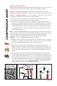
5) Common - Connect the loose end of the Black wire to T1 of the contactor. Check to see that
the Common “C” terminal of the compressor also connects to T1. In most cases you will find
a Black wire coming from the Common “C” terminal of the compressor.
2) Start - Connect the loose end of the Striped wire to the Start winding side of the run
capacitor. The Start winding side of the run capacitor is always marked “HERM”. The Start
winding side of the run capacitor can also be verified by following the yellow or orange or blue
wire (in most cases) from the compressor “S” terminal to the Start winding side of the run
capacitor.
1) Run - Connect the loose end of the Red wire to the Run winding side of the compressor.
The Run winding is connected to T2 of the contactor as well as the common side of the run
capacitor which is usually marked with a “C” or “=”. The Run winding can be identified in most
cases by a Red wire coming from the R terminal on the compressor. The Red wire from the
5-2-1
®
start kit is normally connected at the “C” or “=” terminal on the run capacitor, but can
also be connected to T2 of the contactor. View the illustrations below and scan our QR
codes to learn more about the 5-2-1
®
COMPRESSOR SAVER
®
.
RUN
CAPACITOR
START
C
T1
CONTACTOR
T2
CONTACTOR
R
S
START
CAPACITOR
POTENTIAL
RELAY
52
1
BLACK
RED
UP
STRIPEDSTRIPED
DUAL RUN CAPACITOR
RED
HERM
FAN
C
STRIPEDSTRIPED
# IS Rev D
View Our Technical
Installation Video