
Datasheet


4D SYSTEMS 4D Arduino Adaptor Shield – Hardware Revision 2.xx
© 2014 4D SYSTEMS Page 4 of 8 www.4dsystems.com.au
4D Arduino Adaptor Shield
2. Configuration Options
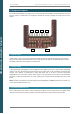
On the 4D Arduino Adaptor, four jumpers (J1, J2, J3 and J4) have been added to provide flexibility to the users
Arduino project, to enable I/O to be changed or disabled as required, including the power source for the
display.
Header 1 (H1) 2.1.
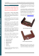
Header 1 (H1) is used to connect the 4D Arduino Adaptor Shield to the 4D Systems display module of choice,
using the 5 way cable supplied with the shield. This cable provides 5V, GND, TX, RX and Reset signals to/from
the display and Arduino, allowing them to communicate.
Header 2 (H2) 2.2.
A 4D Programming Cable/Adaptor connector (H2) has been added which can be used to power the display
module in the case the display being used requires more power than can be provided by the Arduino (for
example if the Arduino is powered off a laptop USB rather than a 5V Jack). If the 4D Programming
Cable/Adaptor isn’t used and an external power supply is, then the RES pin can be used to reset the display
externally, if required. See J1 below. The power supply source is determined by the J2 jumper, please refer
below.
NOTE: The RX and TX Signals from the 4D Programming Cable/Adaptor are NOT passed from this header, it is
used to provide additional power only.
Arduino Reset Button (T1)
2.3.
T1 is a reset button for the Arduino, not for the display. This allows access to the Arduino’s reset button which
may be covered up when a shield in placed on top of the Arduino for a number of the Arduino models.
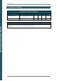
J1
J2
J3
J4
H2
H1