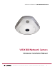
Hardware Install Manual | VISIX 360 Network Camera VISIX 360 Network Camera Hardware Installation Manual 10225 Westmoor Drive, Suite 300, Westminster, CO 80021 | www.3xlogic.
Hardware Install Manual | VISIX 360 Network Camera Thank you for purchasing our product. If there are any questions, or requests, please do not hesitate to contact the dealer. This manual applies to VX-3M-360-IAWD6, VX-6M-360-IA6, VX-3M-360-IAWD, VX-6M-360-IA network fisheye camera. This manual may contain technical inaccuracies or printing errors. The content is subject to change without notice. The manual will be amended if there are any hardware updates or changes.
Hardware Install Manual | VISIX 360 Network Camera 10225 Westmoor Drive, Suite 300, Westminster, CO 80021 | www.3xlogic.
Hardware Install Manual | VISIX 360 Network Camera Regulatory Information FCC Information FCC compliance: This equipment has been tested and found to comply with the limits for a digital device, pursuant to part 15 of the FCC Rules. These limits are designed to provide reasonable protection against harmful interference when the equipment is operated in a commercial environment.
Hardware Install Manual | VISIX 360 Network Camera Safety Instruction These instructions are intended to ensure that the user can use the product correctly to avoid danger or property loss. The precaution measure is divided into ‘Warnings’ and ‘Cautions’: Warnings: Serious injury or death may be caused if any of these warnings are neglected. Cautions: Injury or equipment damage may be caused if any of these cautions are neglected. Warnings Follow these safeguards to prevent serious injury or death.
Hardware Install Manual | VISIX 360 Network Camera Cautions: Make sure the power supply voltage is correct before using the camera. Do not drop the camera or subject it to physical shock. Do not touch sensor modules with fingers. If cleaning is necessary, use a clean cloth with a bit of ethanol and wipe it gently. If the camera will not be used for an extended period of time, put on the lens cap to protect the sensor from dirt.
Hardware Install Manual | VISIX 360 Network Camera Table of Contents APPEARANCE DESCRIPTION ..............................................................................................................................................8 OVERVIEW OF FISHEYE CAMERA ............................................................................................................................... 8 DISASSEMBLING THE CAMERA ..............................................................................................
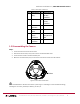
Hardware Install Manual | VISIX 360 Network Camera 1 Appearance Description 1.1 Overview of Fisheye Camera Figure 1-1 Overview of the Fisheye Camera Figure 1-2 Disassembly of Fisheye Camera 10225 Westmoor Drive, Suite 300, Westminster, CO 80021 | www.3xlogic.
Hardware Install Manual | VISIX 360 Network Camera Table 1-1 Description of Overview No. Description No. Description 1 Camera 7 D- D+: Body RS-485 Interface 2 Reset 8 DV-12V: Power Interface 3 Micro SD 9 Audio In Card Slot 4 Camera 10 Audio Out Cover 5 IN G 1A 1B: 11 COAX: Video Alarm Out/Monitor Interfaces Out 6 Ethernet Interface 1.2 Disassembling the Camera Steps: 1. Loosen the lock screw on the camera cover. 2. Remove the camera cover, and you can see the oval dismountable sheet. 3.
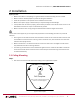
Hardware Install Manual | VISIX 360 Network Camera 2 Installation Before you start: Make sure the device in the package is in good condition and all the assembly parts are included. Make sure all the related equipment is power-off during the installation. Check the specification of the products for the installation environment. Make sure the power supply is matched with your required voltage to avoid damage.
Hardware Install Manual | VISIX 360 Network Camera 2. Fix the three supplied screws half-deep to the ceiling, leaving enough space to hook the camera body. Figure 2-2 Fix the Screws 3. Connect the corresponding power cable, network cable, audio and alarm cables. 4. Align the screw holes to the inserted screws, hook the camera body to the screws, and route the camera body to secure the camera with the screws. 5. Hammer the half-deep screws into the ceiling totally. 6.
Hardware Install Manual | VISIX 360 Network Camera 2.2 Wall/Ceiling Mounting with a Slant Mounting Base(Product #: VX-ISM-360) The wall/ceiling mounting with a slant mounting base provides a wider surveillance view compared to the wall mounting(when positioned correctly). You need to purchase a slant mounting base separately if this mounting method is selected. 3xLOGIC Product Number: VX-ISM-360 Steps: 1. Fix the slant mounting base to the wall with the screws. Figure 2-5 Fix the Slant Mounting Base 2.
Hardware Install Manual | VISIX 360 Network Camera Figure 2-7 Install the Camera Body and Cover Lock Screw Figure 2-8 Tighten the Lock Screw on the Camera Cover 2.3 Wall Mounting with a Junction Box (Product #: VX-SMJ-360) You have to purchase a junction box separately if this mounting method is selected. 3xLOGIC Product Number: VX-SMJ-360 Steps: 1. Fix the junction box to the wall with screws. 10225 Westmoor Drive, Suite 300, Westminster, CO 80021 | www.3xlogic.
Hardware Install Manual | VISIX 360 Network Camera Figure 2-9 Fix the Junction Box 2. Screw the three supplied screws half-deep to the junction box. 3. Connect the corresponding power cable, network cable, audio and alarm cables. 4. Align the screw holes to the inserted screws, hook the camera body to the screws, and route the camera body to secure the camera with the screws. 5. Screw the half-deep screws into the wall totally. 6.
Hardware Install Manual | VISIX 360 Network Camera Lock Screw Figure 2-11 Tighten the Lock Screw on the Camera Cover 2.4 Wall Mounting with a Bracket (Product #: VX-WM-360) You have to purchase the bracket separately if this mounting method is selected. 3xLOGIC Product Number: VX-WM-360 1. Install the bracket to the wall. 2. Install the mounting base to the bracket. 3. Screw the three supplied screws half-deep to the mounting base. Figure 2-12 Install the Bracket 1.
Hardware Install Manual | VISIX 360 Network Camera 3. Screw the half-deep screws into the mounting base totally. 4. Install the camera cover to the camera body, and fix them by tightening the screw on the camera cover. Figure 2-13 Install the Camera Body and Cover Figure 2-14 Tighten the Screw on the Camera Cover 10225 Westmoor Drive, Suite 300, Westminster, CO 80021 | www.3xlogic.