VIGIL Client Software v7.00.
Table of Contents 1 INTRODUCTION ..................................................................................................................................................................... 5 2 SYSTEM REQUIREMENTS .................................................................................................................................................... 6 3 FEATURES...........................................................................................................................
V-POS SETTINGS ........................................................................................................................................................... 43 8.3 General Tab ........................................................................................................................................................................... 43 Database Settings Tab .............................................................................................................................
14.6 DESTINATIONS TAB.......................................................................................................................................................... 80 14.7 AUDIO TAB ...................................................................................................................................................................... 80 14.8 CHAT TAB ......................................................................................................................................
1 Introduction VIGIL Client gives you unrivalled access to live and recorded video from any of your networked DVR’s. Advanced playback and intelligent SmartSearch functionality lets you identify and review events of interest quickly and easily. The result is a more accurate and efficient investigation of incidents with easy export of evidence material. Our mapping function provides unlimited map layers and camera links for unrivaled access to your cameras.
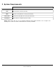
2 System Requirements Recommended Operating System Microsoft Windows XP Professional SP3 or Windows 7 Professional or Ultimate (32 or 64 bit) CPU Intel Core2 Duo, minimum 2.8 GHz RAM Minimum 2 GB (4GB when running Virtual Switch) Video Card PCI Express 1GB (2GB when running Virtual Switch) Hard Drive SATA (Minimum 100MB required for install) Note: VIGIL Client will only run on Windows platforms that support DirectX 7.01 or higher. Run DxDiag.
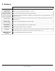
3 Features Details Search Quick Search Regular Playback Retrieve a list of stored footage for specified cameras from a start date/time to an end date/time. Retrieve a list of all footage for the past 1 – 8 hours. Scan through recorded footage using play/pause buttons. Scroll-bar Playback Use a scroll-bar to locate footage by dragging to a desired location, or skim ahead or back 1 or 10 frames per click.
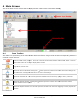
4 Main Screen This is the Main Screen window that is displayed when VIGIL Client has finished loading. 4.1 Icon Toolbar This table is a quick listing of the main toolbar buttons and their usage. Detail of each corresponding window is outlined in later sections. Exits the VIGIL Client program. Click Yes in the Exit Confirmation window to exit VIGIL Client. This will cause VIGIL Client to no longer display alarm events. Logs off the current user. Opens the Servers window.
Opens the Site Map window. You can also open this window from the menu by going to View | Site Map. Opens the Server Alarms window. You can also open this window from the menu by going to View | Server Alarms. Opens the Digital Virtual Switch window. Opens the Settings window. You can also open this window from the menu by going to View | Settings. Clicking the button opens the context menu from which the VIGIL Client settings can be imported or exported. Opens the About 3xLOGIC Inc.
5 Servers Window A Server erver in this context is a DVR PC running VIGIL Server. The purpose e of setting up servers is to make connecting to local and remote servers more efficient than remembering IP addresses or DNS names. Server information is stored by a description that is created by the user. Note: If Managed by VCM is enabled in the Settings, ngs, the Servers list will be populated by the VCM Server the Client connects to. The Servers window displays a list of saved servers.
5.1 Add / Edit a Server Click the Add or Edit (with a Server Selected) buttons from the Servers window to open the Server Settings window. Description A short description or name that will be used to identify this server. IP/DNS Name The IP address or DNS name of the server. To use a dialup connection, leave this setting blank and Enable Use Dialup, select the dialup connection to use from the drop-down menu.
Live Overlay Use Live Overlay From Card Capture Card Input Number Enables live overlay features from an installed capture card to be used. Select the input number from the drop-down menu. Note: For this feature to function properly Live Overlay must be enabled in the Settings | Hardware section and the capture card drivers must be installed. Select the input number for the live overlay from the drop-down menu. Poll Server Data Poll Server Data 5.
Sequence Update Hardware Opens the Sequence window which turns on/off the camera sequencing on connected analog monitors. Note: The sequences must be configured on the Server. Uploads and applies an update file on the server. Select the .VGL update file and the update process will begin. Warning Warning: This action will restart the server and take it temporarily offline. Opens the Hardware Information window which provides some basic information about the Capture Card installed in the VIGIL Server.
Picture Quality Tab The recording quality of each camera can be adjusted on this tab. Simple Settings Tab Adjust the camera recording quality to preset values: Low (20), Medium (40), High (60) and Super-High (80). Advanced Settings Tab Adjust the camera recording quality between 20 and 90. This is for fine-tuning the camera recording quality.
Camera Names Tab The Camera Names tab allows the ability to change the name of each camera. To change the name of a camera, type in the new name beside the camera number and click either Apply or OK. Camera Settings Tab The Camera Settings tab provides advanced configuration of camera parameters, recording mode and rates, and recording CODECs. Select a camera to configure. Camera Default Camera Settings Set the currently selected camera back to default settings.
Recording Mode Sub-Tab The Recording Mode Sub Tab allows for the Recording Speed of the Camera and the Recording Mode to be configured. There are four Recording Mode options encompassing a full range of recording possibilities. These modes are accessible by selecting the appropriate option from the Recording Mode drop-down menu. Set Speeds Constant Motion Opens the Recording Speed window. The recording speed can be set individually for Constant, Motion and Alarm Recording Mode.
Note: The smallest time interval that can be used is a 15 minute period. Const Motion Sets or changes the section to Constant recording mode; these time periods are colored green. Sets or changes section to Motion recording mode; these time periods are colored blue. HZoom+/- Expands and contracts the schedule horizontally; this allows for better precision in setting time periods. VZoom+/- Expands and contracts the schedule vertically.
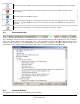
CODEC Settings Tab The CODEC Settings tab allows advanced configuration of the recording CODEC used for storing video footage. Normally, two video encoding CODECs are available for recording video footage: AZTECH and MPEG4, however some models support Hardware CODECs, which have slightly different customization options. AZTECH CODEC Settings The AZTECH CODEC is the default CODEC for most systems. To switch the recording CODEC to AZTECH, select the AZTECH option from the CODEC drop-down menu.
ME Accuracy Motion Estimation Accuracy includes two options: Full Pixel and Half Pixel. Full Pixel checks for motion comparing differences of full pixels. Half Pixel will check for motion using an interpolation method that detects finer movements. Note: Half Pixel is a CPU intensive setting. ME Algorithm The Motion Estimation Algorithm changes the shape of the area used for motion detection and includes two options: Full Search and Fast Search.
Recording Speed Select the desired number of frames per second. Each bank has a set amount of FPS that can be set to its cameras. Values will change depending on the recording speeds for other cameras within the same bank. Network Camera Network cameras are automatically detected and the analog feed is disabled for that camera number. Network camera speeds are independent of other cameras and do not change the maximum allowable FPS for cameras belonging to the same camera bank.
Sequence Tab The Sequence tab configures the camera display sequences for the analog output monitors. Only analog video feeds can be added to a sequence. This is due to hardware limitations on the capture cards. Monitor Number Auto Start Sequence Select the analog output monitor number for the sequence. When enabled, the sequence for the selected analog output monitor is started automatically when VIGIL Server starts. Add Add a new camera to the sequence with a specified dwell time.
Users Tab The Users tab allows the configuration of users on the DVR with specific permissions. Each user belongs to a group and each group has a set of permissions. Users Click the Users button to access the User configuration options. Add a User Edit a User Click the Add button and enter a Username, Group and Password in the Add New user window. Select a User from the Drop-Down Menu and click the Edit button. The user’s group or password can be changed, the user’s name cannot.
Update Tab The Update tab controls the VIGIL Update Service on the remote server. This tool can be used to provide software updates to the server alone or host updates for interconnected VIGIL DVR Systems. Daily Weekly Primary Server A Primary Server provides update files to other systems, but does not receive update files from other systems and does not automatically apply updates locally. Update files must be manually added to the Updates tab.
5.3 Remote Register Opens the Registration window, where you can register software components for the remote server. To obtain registration information for VIGIL Server, record or export the Serial number listed in the registration window. Send the following information to 3xLOGIC at support@3xlogic.com. The serial number or serial number export file. Your Name, Company Name and Contact Information. Details of the modules you wish to purchase.
6 Camera Sidebar The Camera Sidebar consists of three tabs: Sites, Groups and POS/ATM Data (Live). The default view is the Sites tab. 6.1 Sites Tab The standard camera organization is by server site. To view cameras listed by site, ite, click the Sites tab. camera can be viewed in the Live Viewer by double-clicking the camera’s name. A Server site status is indicated by one of these three icons: Site connected with administrator privileges. Site connected without administrator privileges.
Audio Treeview The Audio Treeview shows all configured and currently enabled Audio channels on the connected Server. Double Click Current Channel Sensitivity Stop Double Click on an Audio Channel to Play it Live. Control Volume with the Windows Volume controls. The currently selected Live Audio channel. This slider adjusts the audio sensitivity without affecting the sensitivity settings on the connected server. Click to Stop playing the current Live Audio Channel.
Chat Treeview VIGIL Server and Client include a chat feature to speak or write back and forth between VIGIL Clients connected to VIGIL Servers. The Chat session is initiated by the VIGIL Client only and can be used to communicate via voice or text chat. Double click on Chat in the Treeview to initiate a chat session with the selected Server.
POS/ATM Live Treeview Double Click on the POS/ATM Live Treeview item to open the POS/ATM Data (Live) window for the selected store. Site Name The Site Name is listed in the Title of the window in [ ]. Enter a register number to filter from the POS/ATM data, or leave the entry blank to view data from all data terminals. Filter The POS/ATM Data (Live) window presents Data in tabular form with these columns: • • • • • • • • • Qty. – The quantity of the item purchased. Item – The item purchased.
6.2 Groups Tab Cameras are typically grouped by server site, however, custom camera groups that include cameras from any connected server can be defined. To view custom camera groups, click the Groups tab. Add Group To add a new group, click the Add Group button, enter a name for the new group and click OK. Add To add a camera to a group, click the Add button to open the camera selection screen. Drag and drop the camera onto the group name.
7 Live Viewer Live Viewer Windows each display a Single Camera feed from a connected DVR Server. 7.1 Live Viewer Controls There are two tabs at the bottom of the Cameras Sidebar that contain controls for the Live Viewer windows. Toggles Full Screen Mode. This mode removes the UI and replaces it with a control bar at the bottom of the screen. See Section 7.3 Full Screen Mode for details. Fit All to Screen. This will fit all currently open windows on the screen without overlapping. Cascade Windows.
Maintain Aspect Ratio. When resizing Live Viewer windows, toggle this button to Maintain the Aspect ratio. With this toggled off, the Live Viewer windows can be resized to any size and shape. Close all Live Feeds. Increase all Live Viewer Windows to the maximum speed available for each Camera. Hides/displays the server timestamp in the top left corner of each Live Viewer Window. Opens the OSD Configuration window. See Section 7.4 OSD Configuration for Details. Click to open/close the Camera Control pad.
Priority Audio Analytics If a Priority Audio channel is configured for the camera on VIGIL Server, toggle this option to play live audio. Select which Video Analytics information will be displayed on the live video feed. Speed Select the display speed for the camera. Options are: Slow (1fps), Medium (5fps), Fast (10fps), Turbo (20fps) Maximum, and Frame by Frame Frame. Relays Interfaces to the server relays. Relays can be toggled on or off, corresponding to closed close and open states respectively.
7.4 On Screen Display (OSD) Configuration Dwell Time Number of Lines Background Transparent /Color Font Color/Size/Bold Horizontal/Vertical Offset Column Selection OK 7.5 The number of seconds a data record will remain on-screen. The maximum number of records to display at a time. Change the text background color/transparency. Change the font color/size/boldness. The number of characters to offset the text from the left/top side. Specify which columns to display on-screen.
Dropdown Selection Box This is a menu of all the PTZ cameras configured on the DVR. Select a camera to load for control. Shows/hides additional PTZ camera controls. Use the mouse to click-and-drag the blue dot in the middle of the Pan-Tilt control in the desired direction. The speed at which the camera moves increases as the dot is dragged closer to the edge of the circle. Pan-Tilt The alternate directional controls are displayed when the selected PTZ camera does not support a full range of motion (i.e.
Patterns Control the saved pattern of movement for the selected camera. Patterns are stored within the camera. Select a pattern from the drop-down menu and click Record. Use the other control buttons to move the camera in the desired pattern. Once finished, click Stop. This will overwrite the existing saved pattern. Select a pattern from the drop-down menu and click Run to begin the saved pattern. Tours A tour is a cycle of camera presets. Tour settings are stored within VIGIL Server.
7.6 Recording Modes Colored borders appear around the frame of each Live Viewer Window. These are used to provide a quick assessment of current camera recording modes and events. Green Constant recording mode and is recording. Blue Motion recording mode and is recording (motion detected). Red Alarm recording mode and is recording (alarm triggered).
8 V-POS Treeview Configuration 8.1 V-POS Exceptions V-POS Exceptions are a powerful tool for automating the process of scanning through POS/ATM records looking for Anomalies. Exceptions are automatically checked against the POS/ATM data and when triggered can set off a local or email based report. Add Open the Exception Settings window to create a new Exception. Edit Open the Exception Settings window to edit the selected Exception. Delete Run Delete the selected Exception.
Add / Edit Exceptions Exception Report Description Enter the Description for the Exception. This will show in the Description column in the Event window, the Predefined Exception Query drop down and the Subject line of Emailed reports. Item Case Sensitive Value Whole Dollar Amounts Quantity Code Enter a full or partial item name to search for. To search for multiple items, insert a comma between each item. To exclude an item, insert the test [NOT] before the item name.
Enable this option to enable the use of Video Analytics Rules configured on the VIGIL Server. Combining Video Analytics with Data in Exception Reports allows for powerful Exception reporting such as Customer Not Present during a Refund transaction. Enabled Camera Rule Name Value Scheduled Email Alerts Select the Camera which the Video Analytics rule is configured on. Select the Rule from the list of Rules configured on the selected Camera. Select an operator and input a value.
Local Events 8.2 This feature is enabled by default. When enabled, each occurance of this Exception will have an associated record in the Events Window. If this option is disabled, the Event will not have an associated record. V-POS Events All Exceptions that have the Enable Real Time Exception Events enabled (the default setting) will create an Exception Event for each POS/ATM record that matches the criteria specified in the Exception.
Double click on an Exception Event in the list to open the Playback window. Right Click on an Exception Event to view the following options: Acknowledge Acknowledge All Clear Acknowledge the currently selected Event or Events. If Allow User to Acknowledge all Events is not enabled in the Settings, only one Event can be selected at a time. Acknowledge all Events. If Allow User to Acknowledge all Events is not enabled in the Settings, this button will not be available.
Exception Event Playback Double click on an entry in the Exception Events window, or right click and choose Playback to open the Playback window. Exception Event Playback will have a V-POS Tab available in the Advanced Features Section of the Playback Window. Camera Email V-POS Data V-POS Exception Events can require views from multiple cameras. Select a camera from the drop down list to open another playback window queued up to the same time frame as the Exception Event.
8.3 V-POS Settings The Settings window is where V-POS is configured. Some options are not available for configuration from VIGIL Client. General Tab Limit HTML Reports to X Records Pre/Post Event Buffer Limit max thumbnails to Enter the maximum number of records to load into a report. Note: Although possible, exceeding 10,000 records will seriously affect system response times when trying to load a report.
Database Settings Tab Database Server Location Enter the IP Address, DNS name or Network name of the VIGIL DVR Server. Although it is possible to run V-POS on a different system from the DVR Server, V-POS is designed to work with a single DVR Server and is recommended to be run on the same system. SQL Server Port Number Enter the port number of the SQL Database. The default SQL port number is 1433, we recommend changing the port number from default to port 2025.
DVR Settings Tab DVR server location same as database DVR Server Port User Name / Password Test Connection Check this to indicate that the DVR Server is located on the same system as the V-POS replicated database. This is the recommended installation configuration. If the DVR Server is not located on the same system as the V-POS replicated database, enter the IP Address, DNS name or Network name of the DVR Server. Enter the Data Port for the DVR Server. The default port is 22801.
Event Settings Tab Custom Flags can be created to mark Exception Events in the Event Window. Add / Edit Delete Allow User to Acknowledge all Events Opens the Add / Edit Event Flag window. On that window you can Enter a Name for the Flag and select a custom color for the flag. Click to Delete the selected Flag. Enable this option to allow access to the Acknowledge All button on the Events window, as well as be able to select multiple Events and Acknowledge them with the Acknowledge button.
8.4 V-POS Reports Manual Reporting can be configured using the same criteria as are available for Pre-Defined Exception Events. Manual Reports are presented in easy to read HTML reports that can be Printed, Emailed or Exported. Report Criteria Manual Reports can be created using 3 different methods; a Manual Query, Running a Pre-Defined Exception Event as a Manual Query or Searching for a Specific Transaction. Click the Report Criteria Title bar to Hide / Show the Report Criteria Window.
Search for Line Items Item Case Sensitive Value Quantity Code Enter a full or partial item name to search for. To search for multiple items, insert a comma between each item. To exclude an item, insert the test [NOT] before the item name. If the Load Distinct Items on Startup setting is enabled, a list of valid items will be available from the drop down menu. Enable this option to make the item field Case Sensitive. When enabled, only items matching the case used in the item field will be reported.
Predefined Exception Query Click the Drop Down to select a Predefined Exception Event to use to generate an HTML Report. Only Exceptions with Display in Reports Predefined Exceptions List will be available in this drop down. Search for Transaction by Receipt Receipt # Type in text that will match results in Receipt # column. This Report will only contain the specified Receipt. IDX Type in text that will match results in the IDX column. An IDX# is assigned to each line item in the POS/ATM Database.
Click on a Receipt # Link to filter the report on that receipt number. Receipt # Click on an IDX Link to open a playback window. The time frame for the playback window is determined by the Pre/Post Event Buffer setting. IDX Use this control to navigate through the report pages. Thumbnail Browser Click this button to open the Thumbnail Browser. The Thumbnail browser displays a thumbnail for each individual time stamp in the Report.
9 Digital Virtual Switch The Digital Virtual Switch feature allows users to configure additional PC monitors to display up to 16 simultaneous live camera feeds per PC monitor. Users are able to access and control all cameras from DVR sites, whether they are analog, network, or PTZ cameras, all without the need for a KBD300 keyboard. 9.
9.2 Virtual Switch Screen The virtual switch screen is displayed on secondary monitors with the main monitor reserved for controlling the system without interrupting view of the virtual switch display. Cameras may be added and removed using the keyboard number pad and controlled on-screen using the mouse, or the virtual switch keypad. Under each camera is a control bar containing the virtual switch monitor number, the virtual switch input number, the camera name and the DVR site.
Right-clicking on a monitor in the virtual switch provides a context menu with the following options: Copy Enable On-Screen Display Digital PTZ Priority Audio Analytics Copy a still shot of the video feed to the Windows clipboard. Enables On-Screen display of POS/ATM data. This option will only be available if the camera is configured as a Priority camera for POS/ATM on the VIGIL Server. Enable this feature for zoom and pan control on fixed cameras.
10 Searching VIGIL Client offers a robust set of tools for searching and playing video footage and data. To open the Search window, either click Search on the main VIGIL Client icon toolbar, or select Search | Search Footage and Data from the main menu. Each of the Search window sections can be minimized by clicking the double arrows a section is already minimized, it can be restored using the double arrows. 3xLOGIC’s VIGIL Client - Users Guide Page 54 Doc# 12031914 in the title bar.
10.1 Searching Video Search Reset Performs a search based on the current criteria. Resets all search criteria and POS/ATM data filters to their default values. The From/To time defaults to the past hour from when Reset is clicked. If POS/ATM Data is configured on the VIGIL Server, this button will open the POS/ATM Data Filter POS/ATM Data and Data Search Results sections. Click the POS/ATM Data Filter section title bar POS/ATM data search criteria.
10.2 Searching POS/ATM Data In addition to searching Video Footage, if the server has also been configured to record POS/ATM Data, you can search that data in VIGIL Client. Click the POS/ATM Data button to open the POS/ATM Data Filter section, then click the POS/ATM Data Filter title bar to open the POS/ATM Data search criteria section. Search for Line Items Use the Search for Line Items section to find specific POS/ATM Data within the date and time indicated in the Search Criteria section.
After completing a POS/ATM Data search, a POS/ATM Data Search window will be opened. Note: POS/ATM Data can also be displayed on the Video Playback Window in an OSD Format. The POS/ATM Data Search window presents POS/ATM Data in tabular form with these columns: Qty Item Amount Code Reg # Cashier Receipt # Timestamp IDX The quantity of the item purchased. The item purchased. The price of the item purchased. The transaction type code associated with the transaction. The cash register number.
10.3 Custom Search A Custom Search that includes specified search criteria can be created and saved. The Custom Search window can be accessed from the Presets | Custom Search drop-down menu. It can also be opened from the toolbar menu (Search | Custom Search). When selected, the Custom Search window will appear. Add Opens the Add Custom Search window. Once a Custom Search has been added, click Apply to save the search. Edit Opens the Edit Custom Search window for the selected search.
10.4 Video Playback To play recorded video footage, double-click a camera from the Video Search Results pane. A Playback window will open with the Video Footage Queued up. Multiple Playback and Live Windows can be open at the same time. Information about the camera feed is displayed below the Playback window.
Playback Controls The Playback Controls section of the Playback Window will dynamically change how many buttons are displayed based on the size of the Playback Window. Toggle this button to Sync Playback with all Playback Windows that have this button toggled. Whichever Playback Window is currently selected will become the Master. Click-and-drag the Variable Speed Playback Slider to change the speed of the video playback.
Advanced Playback Controls Click the button on a Playback Window to expand the Advanced Features Controls. If the button is not visible, drag the Playback Window w larger to display all buttons. Smart Search Tab The Smart Search feature refines the loaded v video footage based on motion ion detected within a user-defined user region. To perform a Smart Search, you must first define or “mask” a motion detection region. To do this, click Show Mask and draw on the playback image.
Zoom Tab Playback footage can be zoomed by selecting the Zoom tab from the Advanced Features section. Click the Zoom In / Out buttons to zoom the playback window in and out. The Zoom will be focused on the current center of the window. When the cursor is moved over the Playback window, a zoom outline will be displayed to indicate the region that will be magnified.
Markers Tab During playback, if only a sub-range of the loaded footage is of interest it can quickly be selected by using Markers. To use Markers, select the Markers tab from the Advanced Features section. Start / End Range Position the footage navigation slider at the beginning of the subrange and click the Start Range button. You will notice a small marker appear below the starting point. Next, navigate to the end of the sub-range and click the End Range button. Clear Removes the sub-range markers.
Audio Tab If audio recording is enabled and configured in the DVR settings, the Audio tab will become available in the Advanced Features section of the Search window. Selecting an audio channel from this tab allows you to playback recorded audio along with video footage. To choose which audio channel to playback, select the channel from the drop-down menu in the Audio tab.
Playback Right-click Menu: Remove Copy Closes the Playback Window. Copies a still shot of the current image to the Windows clipboard. If the image is zoomed in, a Copy Zoomed option will be available as well. For cameras using the Panorama PTZ camera control type, the video can be manipulated in the playback window using the following right-click menu options: Source Video Only (Rotate Disabled) This option is enabled by default. This feature allows users to zoom in and move cameras during playback.
11 Exporting Video footage can be saved either as a single frame still shot or as a video file. Audio and POS/ATM data can be saved either embedded within video footage or in a separate document. This process is referred to as “exporting”. Note: To export footage there must be at least one export destination configured. Note: If Export Auditing is enabled on the DVR, required information must be entered before selecting the destination folder for both images and video exports. 11.
11.2 Video Exporting Video footage can be exported in Microsoft AVI Video format or in Authentic Video format which uses 3xLOGIC’s Motion JPEG AZTECH format. Video clips exported in Authentic Video format can be played using the 3xLOGIC DV Player program. AVI format video clips can be played using Windows Media Player or any other player that supports standard AVI format.
11.3 Audio Exporting Click the export button and select Audio as WAV File. This will allow you to export audio in .wav format with no accompanying video footage, Use the From and To date and time boxes to select the range of the audio footage to export, and select the audio channel to export from the Channel drop-down menu. Note: To export audio, an audio channel must be configured on the VIGIL Server. 11.
Copy a Folder Right-click on a folder in the File Browser and select Copy item(s). You can also use the menu to copy a folder by selecting the folder and going to File | Copy item(s). Note: To select multiple folders, hold down the Control key as you make your selection. Delete a Folder Right-click on a folder in the File Browser and select Delete item(s). You can also use the menu to delete a folder by selecting the folder and going to File | Delete item(s). Only empty folders can be deleted.
12 Site Map The Site Map utility provides a graphical interface to a site’s cameras by displaying their location on a map. For more information on creating and using site maps, please refer to the Site Map Designer Section. Monitor Live Select an analog output monitor on the DVR that will display the camera. Displays cameras in the Live Viewer window. Toggles the playback controls: Reset – Resets the search criteria to default (previous hour). Play Quick Retrieve – Search from preset time intervals.
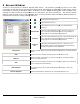
13 Server Alarms VIGIL Server DVRs can be configured to send alarms to VIGIL Clients. The IP address of the client computer must be entered in the VIGIL Server settings before it is able to receive alarms. Please refer to the VIGIL Server User’s Guide for details. When VIGIL Client receives an alarm, the Server Alarms window is displayed. The Server Alarms window provides a listing of alarm events and allows quick playback of alarm footage.
In the alarm right-click menu all of the above features are available as well as the Export Image feature. Once an alarm thumbnail has been opened the Export Image feature will become available. When selected, the Select Destination window displays where the user can choose an export destination to save a copy of the thumbnail image. 13.1 Preview Alarms Click on the thumbnail icon in the Preview column to show a thumbnail snapshot image of the alarm event. Click on the expanded thumbnail to minimize it.
13.3 Search Alarms Click alarm event. to open the Search Alarms window where a variety of criteria can be used to search for an Click Search to search for all alarm events on the system. following options. From/To Site Alarm Type The results can be narrowed down with the Check the From and/or To box and enter the time range to search for alarm events. Select the Site to search alarms from. Check this box and select an alarm type to search for from the drop-down menu.
14 Settings 14.1 Startup Tab The Startup tab controls the behaviour of VIGIL Client when it first opens. Show Splash Screen on Startup Enable Client Login Connection Timeout Auto Logon to All Servers on Startup When enabled, VIGIL Client automatically connects to all servers when the program is launched. Display All Available Cameras When enabled, VIGIL Client will launch up to 36 available cameras in the Classic Live Viewer. This feature requires Auto Logon to All Servers on Startup to be enabled.
VCM Name Enter a Descriptive Name for the VCM Server, this name will show in the Connection window when Client is launched. IP Address Enter the IP Address for the system the VCM Server Service is running on. Port Enter the Port for the VCM Server Service. The default is 10507. VCM User Name / Password Enter a Valid Username and Password that exist on the VCM Server. The list of DVR Servers provided by the VCM Server will be based on the permissions of the VCM User.
14.2 Live Tab The Live tab controls how the Live Viewer windows function. Frame by Frame Enables faster decoding of streams from MPEG4 cameras. Note: This setting may have an adverse effect on non-MPEG4 cameras. Transfer Motion Block Enables the transfer of motion block information for use with the SDK. Note: Enabling this feature is not recommended.
14.3 Search Tab The Search tab controls how searching of Video Footage and POS/ATM data functions. Stream Simultaneously Enables VIGIL Client to stream live footage and playback recorded video footage simultaneously. To conserve server resources, leave this option disabled. Alarm Playback Pre Event Set the amount of time to playback prior to an Alarm when playing Alarm footage in the Server Alarms window.
Look Ahead This is the size of the buffer, in number of frames. Settings from 30 to 1800 frames are available. It is recommended that a higher cache size is used for a higher frame rate. When searching footage, this feature stores the footage in the configured cache location. If the footage already exists in the cache, the cached footage is displayed instead of retrieving the footage again from the server. Enable Playback Disk Caching Cache Location The location where the cached files will be stored.
Automatically Display Alarms In Live View When enabled, the live camera feed corresponding to an alarm event will automatically be displayed in the Live Viewer window. If the live view layout is full, the camera feed will replace another that does not currently have an alarm event. If the site is not connected, it will reconnect and display the live camera feed. Maximum Alarm Records Set the maximum number of alarms to display in the Server Alarms window.
14.6 Destinations Tab Video Still/Motion Export Destinations are used to store exported video footage. You must set up destinations here before you can save video footage or still images. When an export destination is added or edited, the Media Control window is displayed. Destination Name Destination Path The name for the export destination. The path for the export destination. Click ... to browse to the destination. This setting affects how the destination appears in the export list.
14.9 Sitemaps Tab The Sitemaps tab instructs VIGIL Client where to locate sitemap files. Top Level Maps Location 14.10 Enter the path to the top level sitemaps or click the button to browse to the location. Transcoder Tab The Transcoder tab allows configuration of up to four video transcoders to recode video and display it on an analog monitor. For more information, please contact 3xLOGIC. Constant Quality/Bitrate Deinterlacing Register, Control, Streaming Ports 14.
Digital Virtual Switch Show Timestamp Show Record Status Stretch Image to Fit Window Displays the video time on the monitor output screen. Displays coloured camera borders that indicated the recording mode on the monitor output screen. Blue for motion, yellow for dwell time, green for constant, and red for alarm. Stretches the camera image to fit the virtual switch monitors (i.e. camera spots).
Analog Virtual Switch Note: Analog Monitor Output is not supported on Microsoft Windows 7 or Microsoft Windows Vista operating systems. Video Standard Choose to use NTSC or PAL as your monitor output video standard. NTSC is the analog television system used in Canada and the United States (among some other countries). Configure OSD Show Camera Name Displays the camera name on the monitor output screen. Show Site Name Displays the Site Name on the monitor output screen.
Virtual Switch Input Mappings Opens the Virtual Switch Input Mappings window where you can add, edit, delete, auto map, or print virtual switch input mappings. This feature allows you to view the mapped cameras using the VIGIL Client Virtual Switch control pad or a KBD300 by entering the monitor number and virtual switch input number.
15 Site Map Designer The Site Map Designer is a utility that allows the user to configure graphical displays of the site with associated cameras. To open the Site Map Designer, from the Start Menu: Programs | VIGIL | Site Map Designer. Creating a New Site Map 1. Before beginning a new site map, create an image (JPG or BMP) file. This file will be used as a background picture for the site map. 2. Click the Image button on the toolbar or select File | Load Background Image from the menu.
15.1 Site Map Designer Icons and Buttons Hot Spot With this icon selected, drag a box on the site map to define a new hot spot. To delete a hot spot, select the hot spot you wish to remove and click the Delete key. Fixed Camera Select an existing hot spot on the sitemap and then click the icon or drag a box with the icon selected to place a fixed camera on the site map. When setting up these cameras, specify the appropriate remote host and camera number in the control settings.
15.2 Site Map / Hot Spot Properties Note: Click the Tab key or select a different input box after each setting has been made to make sure the changes occur. Sitemap Properties Description Top Level Map A brief description of the site map. Top Level Maps are listed as a home map in Gatekeeper. Hotspot Properties Default Live Only Hot Spot Types Link Relay Caption Tag Top / Left / Width / Height Matrix Input Link Map Select Default for a PTZ or a fixed camera hotspot.
16 DV Player VIGIL Client allows video exports to include the VIGIL DV Player to ensure playback software is available for Authentic Video (MJPG) exports. A number of controls have been provided to make navigation and advanced features more accessible: Click and hold down the Fast Backward or Fast Forward button to playback as quickly as possible without skipping any frames. Skips to the very beginning/end of the video footage. If clicked while playing the footage, skips one 10th of the footage.
If Video Analytics information has been embedded in the Video File, what information is displayed can be selected. Save a still image in BMP or JPG format, export video in AVI, Authentic Video (MJPG) or VIGIL Server File Stream format, or Audio only. Select Print Still Image to print the current frame or select Print Data to print the currently displayed data. Rotate the video 90 degrees in the indicated direction. To zoom in, move the cursor over the video.
17 Language Switcher VIGIL Client can be run in English, French, Spanish and Hebrew. The Language Switcher can be run from Windows Start menu, select Programs | VIGIL | Language Switcher. Select the desired language from drop-down menu, click switch. A prompt will show informing that a system reboot is required to complete language change. Click Yes to reboot immediately, Click No to have the update applied the next time system is restarted.
18 Contact Information 3xLOGIC has offices in Victoria BC, Canada and in Westminster Colorado, USA. Please visit our 3xLOGIC web site at www.3xlogic.com. Please contact us by e-mail at support@3xlogic.com (technical support), or using the following contact information: 3xLOGIC Technical Support: Toll Free: (877) 3XLOGIC (877) 395-6442 Email: support@3xlogic.com Website: www.3xlogic.