
User Manual
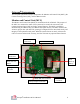
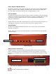
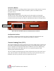
Table Of Contents

Octopus Installation & User Manual
4
Octopus System Description
System Overview
The 3SI Octopus ATM Defense System is a patented wireless system designed to
protect automatic teller machines (ATMs) from theft (pull-out) and break-in attacks. The
system is comprised of three main components: a Monitor and Control Unit (MCU), up
to 6 Cassette Staining Units (CSU), and an iButton Key Reader. The MCU is located in
the main ATM safe area, and monitors the ATM for theft or break-in. The CSU is located
within the currency cassette, and provides the ability to stain the currency in the event of
attack - thus rendering the money useless to the attackers. The iButton Key Reader
provides a secure method of accessing and controlling the MCU state (as defined below),
and contains an LED to provide status of the present operational state (see below). The
system is designed for continuous monitoring and protection of cassette-based ATM
currency for a period of two years without system maintenance or service interruption.
The MCU is powered by a plug-in Power Adapter, but also has an internal rechargeable
battery which will provide backup in case of power loss. The CSUs are powered by an
internal battery pack which provides maintenance free operation for a full two years. The
small dimensions of the MCU allow it to be placed almost anywhere within the ATM
safe, while the small bracket design of the CSU allows for fast field installation with
minimal cassette modification.
The Octopus system offers two modes of protection:
Auto-Arm mode - Auto-Arm mode is the default mode, and provides for theft
(pull-out) protection only.
Door-Bolt mode - Door-Bolt mode is optional, and provides additional protection
against break-in by monitoring the proper opening/closing of the door dead-bolt.
The door-bolt option must be specified at the time of ordering since additional
installation components are required.
The Octopus system offers several optional features to enhance the detection and alarm
capabilities of the system. (Refer to Appendix F for details.)
Operational States
The Octopus system has 5 operational states: Disabled, Enabled, Arming Delay, Armed,
and Activation. Each of these states is indicated by a specific iButton LED color:
Disabled State – LED Off
When in the Disabled state, the system is essentially OFF and will not monitor for an
ATM attack. The Disabled state is the only state in which serial communications can be
established with the MCU via the computer serial port.