™ ™ 3M Speedglas 9100 User Instructions Bedienungsanleitung Notice d’instructions Инструкция по эксплуатации Інструкція з експлуатації Instruzioni d’uso Gebruiksaanwijzing Instrucciones de uso Instruções de uso Bruksanvisning Bruksanvisning Brugsanvisning Käyttöohjeet Kasutusjuhend Vartotojo žinynas Lietošanas instrukcija Instrukcja obsługi Pokyny Használati utasítás Instrucţiuni de utilizare Navodila za uporabo Užívatel’ská príručka Upute za uporabu Қолданушының нұсқаулығы Инструкции за използване Kull
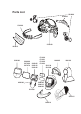
Parts List 53 60 00 53 62 00 53 6100 53 30 00 16 80 15 53 20 00 52 60 00 52 70 00 52 70 70 50 00 05 50 00 15 50 00 25 17 10 20 17 10 21 17 10 22 17 10 23 16 90 05 16 91 00 50 11 90 50 18 90 52 80 05 52 80 15 52 80 25 42 20 00 53 10 00 53 20 15 16 90 10
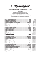
User manual 3M™ Speedglas™ 9100 0196 Notified body 0196 DIN CERTCO Prüf- und Zertifizierungszentrum Aalen Augenschutz und Persönliche Schutzausrüstung Gartenstraße 133, 73430 Aalen, Germany 1ï User Instructions ............................................... page 3 Bedienungsanleitung .............................................. Seite 2 Notice d’instructions ............................................... page r ɂɧɫɬɪɭɤɰɢɹ ɩɨ ɷɤɫɩɥɭɚɬɚɰɢɢ ....................... ɫɬɪɚɧɢɰɚ u ȱɧɫɬɪɭɤɰɿɹ ɡ ɟɤɫɩɥɭɚɬɚɰɿʀ .......
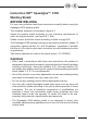
1ï Instruction 3M™ Speedglas™ 9100 Welding Shield BEFORE WELDING For your own protection read these instructions carefully before using the Speedglas 9100 welding shield. The complete assembly is illustrated in figure A:1. Adjust the welding shield according to your individual requirements to reach the highest comfort. (see figure B:1 - B:4). Shade number should be chosen according to table on page 250.
1ï • The manufacturer is not responsible for any modifications to the welding filter or use with welding shields other than the Speedglas 9100 welding shield. Protection may be seriously impaired if unsuitable modifications are made. • Wearers of ophthalmic spectacles should be aware that in the case of severe impact hazards the deformation of the shield might cause the inside of the shield to come into contact with the spectacles creating a hazard for the wearer.
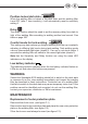
1ï If the protection meets the requirements at extremes of temperature (-5°C to +55°C) the marking is completed with the letter T. Additional markings on the product refer to other standards. FUNCTIONS On/Off To activate the welding filter, press the SHADE/ON button. The welding filter automatically turns OFF after 1 hour of inactivity. The welding filter has three photo sensors (see fig A:2) that react independently and cause the filter to darken when a welding arc is struck.
1ï Sensitivity The programming and sensitivity of the photo detector system (which responds to the light from the welding arc) can be adjusted to accommodate a variety of welding methods and workplace conditions. In order to see the current sensitivity setting, momentarily press the SENS button. To select another setting, press the SENS button repeatedly until the LED shows the desired setting.
1ï Position locked dark state When the welding filter is locked in the dark state and the welding filter turns OFF (after 1 hour inactivity), it will automatically reset to sensitivity setting 2. Delay The delay function should be used to set the recovery delay from dark to light of the welding filter according to welding method and current. See table on page 250. Comfort mode for tack welding.
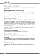
1ï Replacement of welding filter The welding filter can be removed and replaced according to figure C:1 and E:1 - E:2. Replacement of inner protection plate The welding filter must be removed to replace the inner protection plate. The used inner protection plate is removed as illustrated in figure D:1. The new inner protection plate should be inserted after the protective film is removed as illustrated in figure D:2. Magnifying lens (accessory) mounting (see figure D:3).
1ï Temperature range The recommended operating temperature range for the product is -5°C to +55°C. Store in a clean and dry environment, temperature range -30°C to +70°C and relative humidity less than 90%. Inspection The sensors (see fig A:2) on the welding filter must be kept clean and uncovered at all times for correct function. To check that the electronics and buttons are working, press the buttons and the LED indicators will flash.
1ï Parts List 3M™ Speedglas™ 9100 Part no.
Technical Specification Weight: Welding shield with SideWindows (excl headband and welding filter): Welding shield w/o SideWindows (excl headband and welding filter): Headband Welding filter: Speedglas 9100V Speedglas 9100X Speedglas 9100XX 265 g 240 g 120 g 150 g 160 g 185 g Viewing area: Welding filter: Speedglas 9100V Speedglas 9100X Speedglas 9100XX UV/IR protection: Switching time light to dark: Opening time dark to light (delay) Light state: Dark state: Fail safe state: Battery type: Operating temp
A:1 A:2 A:3 B:1 243
B:2 1. B:3 244 2. 3.
B:4 245
C:1 C:2 C:3 246
D:1 D:3 D:2 E:1 E:2 247
F:1 F:2 F:3 248
G:1 H:1 H:2 249
Recommended shade numbers according to EN 379:2003 Delay (recovery delay) Delay Shade 0,1 *) d1 d2 ∑ d1 d2 delay shade 12 5 40 40 60 90 130 8 40 40 60 100 150 9 40 40 60 100 150 200 300 500 375 625 1000 10 40 40 70 150 200 300 300 600 425 625 1050 11 50 50 80 200 300 375 325 700 475 625 1100 12 50 50 90 250 400 475 325 800 575 625 1200 13 60 60 100 300 450 525 325 850 675 625 1300 200 s m ∑ shade 12 300 250 400 shade3 shade3
ï 3M Ireland 3M House, Adelphi Centre Upper Georges Street Dun Laoghaire, Co. Dublin Tel: 1800 320 500 www.3m.com/uk/ohes - 3M Portugal Rua do Conde de Redondo, 98 1169-009 Lisboa Tel: 213 134 505 Fax: 213 134 693 3 3M Deutschland GmbH In der Heubrach 16 63801 Kleinostheim Tel: 0 60 27 / 46 87 - 0 arbeitsschutz.de@mmm.com www.3marbeitsschutz.de % 3M Östereich GmbH Brunner Feldstraße 63 2380 Perchtoldsdorf Tel: 01/86 686-0 arbeitsschutz-at@mmm.com www.3m.