3 Dynatel™ Advanced Modular System 965AMS Version 4.01.
Contents Introduction......................................................................................5 Getting Started...........................................................................................5 Welcome Screen.........................................................................................7 Help............................................................................................................7 High Voltage................................................................
System Modes........................................................................................191 AC Charger............................................................................................192 DC Charger............................................................................................192 Level of Charge......................................................................................193 System Reset...............................................................................
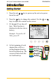
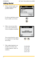
Introduction 3M™ Dynatel™ Advanced Modular System 965AMS Introduction Getting Started 1. Press the red down the unit. key to power up the unit or to power 2. Press the key to change the contrast. Use the keys to adjust the contrast on the screen. or 3. F1 through F5 are the soft keys. Their function is displayed in the box above the key. Example: To use the AC Volts, press F5. 4. At the beginning of each chapter there will be a wiring diagram showing the test lead hook-up.
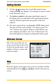
Introduction Getting Started 5. Some screens require you to choose from a list of possible choices. Use the up and down arrow keys to make your choice. 6. Other screens may allow you to enter information such as telephone numbers. You can position the cursor by using the Left and Right arrow keys. 7. This symbol indicates you should use the blue keys to enter numeric values or numbers.
3M™ Dynatel™ Advanced Modular System 965AMS Introduction Getting Started 8. Use the (escape) key to quit the current screen without making any changes. Use multiple escapes to return to the Welcome screen. 9. The battery symbol in the upper right-hand corner of the display gives an indication of the approximate battery capacity. Each bar represents one-quarter of the full capacity. 10. The unit is powered by a rechargeable NiMH battery pack. The unit will also work with the “AA” battery pack.
Introduction High Voltage This screen indicates a high voltage (120 VAC/VDC or greater) has been detected between the test leads when not in the Voltage Mode. The tester has opened an internal relay to protect itself from damage. Use standard safety practices for disconnecting the test leads since high voltage may be present. Press OK to restart the 965AMS tester.
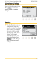
3M™ Dynatel™ Advanced Modular System 965AMS System Setup System Setup Start with the Welcome Screen. Press Setup to review the global settings or to make changes. Country 1. Use the Country setup to configure the tester for a specific country. Selecting a new country will configure the tester with the setups for language, units, clock format, wire gauges, and cable types for that particular country. Press Change to make changes or to review the current settings.
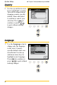
System Setup Country 2. Use the up and down arrow keys to highlight a country. You will be warned about changing country-specific default values and asked to confirm or cancel your selection. Press OK to continue or press to quit without making changes. Language 1. Use the Language setup to change only the language in the tester. Countryspecific default values are not affected. Use the up and down arrow keys to highlight a new language. Press OK to continue or press to quit without making changes.
3M™ Dynatel™ Advanced Modular System 965AMS System Setup Module 1. Use the Module setup to select the type of module that is installed in your tester. The module type is listed on the label on the module. Use the up and down arrow keys to highlight Module. Press Change to make changes or to review the current settings. Network Setup 1. Use Network Setup to change network options used to connect to computers or ADSL circuits. Use the up and down arrow keys to highlight Network Setup.
System Setup Units 1. Use the Units menu to change the Units of Measure. Use the up and down arrow keys to highlight Units. Press Change to continue or press to quit without making changes.
3M™ Dynatel™ Advanced Modular System 965AMS System Setup Units 2. Use the up and down arrow keys to select the units you want to change. Press Change Selection to change the units of measure. An “X” in a box indicates your choice. Distance: Feet or Meters: This affects all distances displayed in the 965AMS tester. Degrees: Fahrenheit or Centigrade: This affects all temperatures used in the 965AMS tester. Filter: C-Message or CCITT: This affects the filter used in the POTS Noise function.
System Setup User Info 1. Select User Info to add your Tech ID and job number to be added to saved test results. Use the up and down arrow keys to highlight User Info. Press Change to make changes or to review the current settings. 2. Use the blue keys to enter your ID, name, etc. Press Select Job ID to highlight the Job Num field. Use the blue keys to enter a job number or ID. Press OK to continue or press to quit without making changes.
3M™ Dynatel™ Advanced Modular System 965AMS System Setup Clock Settings 1. Use the Clock Settings menu to select the clock format and to set the correct time. Use the up and down arrow keys to highlight Units. Press OK to continue or press to quit without making changes. 2. Use the blue keys to enter the correct date.
System Setup Clock Settings 3. Press Select , then enter the correct time using the blue keys. 4. Press Select to enter the date format. Choose month, day, year or day, month, year.
3M™ Dynatel™ Advanced Modular System 965AMS System Setup Clock Settings 5. Press Select to choose the 12-hour or 24-hour format. Use the up and down arrow keys to select the format. If you choose the 12-hour format, press a.m. or p.m. . Note: Press OK at any time that you have completed your updates.
System Setup 3M™ Dynatel™ Advanced Modular System 965AMS Set Beep Volume 1. Use this menu to change the Set Beep Volume. Use the up and down arrow keys to highlight Set Beep Volume. Press Change to continue or press to quit without making changes. 2. Use the up and down arrow keys to change the beep volume. Press OK to save this volume setting.
3M™ Dynatel™ Advanced Modular System 965AMS System Setup Power Down Timeout 1. Use this menu to change the Power Down Timeout. Use the up and down arrow keys to highlight Power Down Timeout. Press Change to continue or press to quit without making changes. 2. Use the up and down arrow keys to select the timeout you want to use. Press OK to save your choice.
System Setup 3M™ Dynatel™ Advanced Modular System 965AMS Custom Cable Use Custom Cable 1 or Custom Cable 2 to create a special cable you are using on a regular basis that has capacitance values that are different from existing cables. You can also access this function in the Opens Setup menu. 1. Press the blue key to enter the Opens measurement function. 2. Press Setup to enter the Setup menu. 3. Use the up and down arrow keys to select Custom 1 or Custom 2. Press 20 Edit Custom .
3M™ Dynatel™ Advanced Modular System 965AMS System Setup Custom Cable 4. Use the blue keys to enter the capacitance to ground. Press Select Mutual . 5. Use the blue keys to enter the mutual capacitance. Press Select Ohms .
System Setup 3M™ Dynatel™ Advanced Modular System 965AMS Custom Cable 6. Use the blue keys to enter ohms per thousand feet. Press . Select Velocity 7. Use the blue keys to enter the velocity propagation. If you do not know this value, use 0.68. Press 22 Select Cable .
3M™ Dynatel™ Advanced Modular System 965AMS System Setup Custom Cable 8. Use the up and down arrow keys to select Custom 1 or Custom 2. Press OK to save the custom cable.
System Setup 3M™ Dynatel™ Advanced Modular System 965AMS Voltage Termination 1. The Voltage Termination option allows you to select the input impedance of the 965AMS digital voltmeter (in supported countries only). The input impedance of the internal 965AMS voltmeter is normally 1Mohm. However, some legacy systems use voltage measurement systems with input impedances of 100Kohms. This option is provided to maintain measurement compatibility with those systems.
3M™ Dynatel™ Advanced Modular System 965AMS System Setup Voltage Termination 2. Use the up and down arrow keys to select the Voltage Termination you want to use. Press OK to save your choice.
Measurement Functions 3M™ Dynatel™ Advanced Modular System 965AMS Measurement Functions The 12 measurement functions include: DC and AC voltage measurements milliAmps and ground resistance measurements Ohms measurement and Soak Test elf-Calibrate, Stored Results and Ohms-to-Distance S Calculator Opens distance measurement Send Tones esistance Fault Locate: Distance measurement to a R resistive fault SL Loss and Noise plus the Spectrum Analyzer and D Resistance Balance Time Domain Reflectrometer (TD
3M™ Dynatel™ Advanced Modular System 965AMS Measurement Functions Volts-DC or AC The Volts function measures the DC voltage or AC voltage between Tip, Ring and Ground. Volts-DC or AC>Hook-Up RED Ring (B) GRN Ground (Earth) BLK Tip (A) Volts-DC or AC>Operation key 1. Press the blue to start the voltage measurement function. 2. This screen displays the T-R voltage in the larger active measurement box. 3. Press Tip Gnd to display the T-G voltage.
Measurement Functions 3M™ Dynatel™ Advanced Modular System 965AMS Volts-DC or AC>Operation 4. Press Ring Gnd to display the R-G voltage. The T-G measurement will be saved on the screen in a smaller box until a new measurement updates the screen. 5. All measurements are erased when you exit this function. Volts-DC or AC>AC Volts 1. Press AC Volts to measure AC volts. AC Normal Range—Active Line: 1. R-G and T-G should have the same AC voltage. If they are not equal the pair will probably have noise. 2.
3M™ Dynatel™ Advanced Modular System 965AMS Measurement Functions Loop Current Loop Current measures the loop current in an active line. Loop Current>Hook-Up RED Ring (A) BLK Tip (B) Loop Current>Operation 1. Press the blue start this test. key to 2. This is a continuous measurement until you disconnect the test leads or choose another function.
Measurement Functions 3M™ Dynatel™ Advanced Modular System 965AMS Loop Current>Operation 3. Over Current Warning The tester has detected a current greater than 110 mA. Over current can damage the test set. Use standard safety practices for disconnecting the test leads and eliminating the source of the over current. Disconnect all test leads then press Retest to continue.
3M™ Dynatel™ Advanced Modular System 965AMS Measurement Functions Loop Current>Ground Resistance>Operation 1. Press the blue start this test. key to Gnd Resistance Press to access the Ground Resistance function. 2. Press Test to start the test. The results will be displayed in the box in the center of the screen. 3. This is not a continuous test. Press Test to see an updated result.
Measurement Functions 3M™ Dynatel™ Advanced Modular System 965AMS Ohms Measurements The Ohms Measurement function measures the insulation resistance between the Tip, Ring and Ground. This function can also measure the resistance of the Tip and Ring loop or individual wires. Ohms Measurements>Hook-Up RED Ring (B) GRN Ground (Earth) BLK Tip (A) Ohms Measurements>Operation key to 1. Press the blue start the ohms measurement function. 2.
3M™ Dynatel™ Advanced Modular System 965AMS Measurement Functions Ohms Measurements>Operation 3. Press Tip Gnd to display the Tip-Ground resistance. The T‑R measurement will be saved on the screen in a smaller box until a new measurement updates the screen. 4. Press Ring Gnd to display the Ring-Ground resistance. The T‑G measurement will be saved on the screen in a smaller box until a new measurement updates the screen. 5. All measurements are erased when you exit this function.
Measurement Functions 3M™ Dynatel™ Advanced Modular System 965AMS Ohms Measurements>Voltage Compensation The Voltage Compensation feature compensates for crossed battery on the line. Use “compensated” for most measurements. Press V Comp to turn voltage compensation off and on. The screen displays “Compensated” or “Not Compensated.
3M™ Dynatel™ Advanced Modular System 965AMS Measurement Functions Ohms Measurements>Soak Test 1. Take an initial resistance measurement by pressing the Snap Shot key. 2. You will compare this to other active measurements to determine the source of the fault. 3. One of the properties of moisture in a circuit is that the current from the tester can “dry out” the moisture. The display will first show a lower resistance, then after one or two minutes the resistance will increase to a higher reading.
Measurement Functions 3M™ Dynatel™ Advanced Modular System 965AMS Ohms Measurements>Soak Test 4. A property of corrosion is that a current flowing through the corrosion will cause the corrosion to become a better conductor. The display will show a lower resistance reading if corrosion is the cause.
3M™ Dynatel™ Advanced Modular System 965AMS Measurement Functions Ohms Measurements>Soak Test 5. If the resistance value does not change, the fault is a pure resistive fault. 6. Use Go To Positive Voltage and Go To Negative Voltage to reverse the voltage polarity. Use the lowest resistance reading of the two numbers for your measurements.
Measurement Functions 3M™ Dynatel™ Advanced Modular System 965AMS Toolbox Use the Toolbox to: (1) view saved test results, (2) perform a self calibrate, (3) use the Ohms to Distance calculator, (4) use Internet Explorer and (5) Upload results to the 965AMS Results Manager. Toolbox>Stored Results The Stored Results function allows you to review the results of previously saved tests. Toolbox>Stored Results>Operation key to 1. Press the blue enter the Toolbox function.
3M™ Dynatel™ Advanced Modular System 965AMS Measurement Functions Toolbox>Stored Results>Operation 2. If one or more test results have been stored, the ID number for each will be displayed. The ID number is like a file folder and each test result is like a file. The name of the file is the time and date stamp that is generated by the tester. Press View to see the list of files. 3. This screen shows the contents of the file.
Measurement Functions 3M™ Dynatel™ Advanced Modular System 965AMS Toolbox>Self-Calibrate The Self-Calibrate function will verify that all of the internal circuits and test leads are operating properly. Use self-calibrate: • After the first full battery charge before you put the tester in service for the first time. • Anytime the working temperature changes by more than 35°F (20°C). Calibrate the 965AMS tester at the same temperature at which it will be used.
3M™ Dynatel™ Advanced Modular System 965AMS Measurement Functions Toolbox>Self-Calibrate>Operation key to 1. Press the blue enter the Toolbox function. 2. Use the up and down arrow keys to select the SelfCalibrate function. Press OK to save your choice. 3. The calibration may take up to 1 minute to complete.
Measurement Functions 3M™ Dynatel™ Advanced Modular System 965AMS Toolbox>Ohms-to-Distance Calculator Use this function to convert from Ohms to Distance or Distance to Ohms based on temperature and wire gauge. Toolbox>Ohms-to-Distance Calculator>Operation key to 1. Press the blue enter the Toolbox function. 2. Use the up and down arrow keys to select the Ohms-toDistance Calculator. Press OK to save your choice. 3. Use the blue keys to enter the Ohms value.
3M™ Dynatel™ Advanced Modular System 965AMS Measurement Functions Toolbox>Ohms-to-Distance Calculator>Operation 4. Use the up and down arrow keys to select the wire gauge. Press Select to save and highlight the temperature field. 5. Use the blue keys to enter the temperature.
Measurement Functions 3M™ Dynatel™ Advanced Modular System 965AMS Toolbox>Ohms-to-Distance Calculator>Operation 6. Press Convert to find the distance. 7. Select Distance to Ohms if you want to convert a distance to an Ohms value. Internet Explorer 1. Internet Explorer is available on the VDSL2 module. 2. Use the up and down arrow keys to select Internet Explorer. Press OK to save your choice.
3M™ Dynatel™ Advanced Modular System 965AMS Measurement Functions Toolbox>965AMS Results Manager The 965AMS tester uses the 965AMS Results Manager to upload and convert files from the tester. The following files are supported by the 965AMS Results Manager: • Single Trace TDR • Active POTS Autotests • Vacant POTS Autotests • Wideband Autotests • xDSL Link Metrics • xDSL Bin Graphs Note: Only results listed above will be converted using the 965AMS Results Manager.
Measurement Functions 3M™ Dynatel™ Advanced Modular System 965AMS Toolbox>965AMS Results Manager>Connections 1. Turn on the 965AMS tester and allow the unit to boot up. 2. Connect the 965AMS tester to power. 3. Connect the 965AMS tester to the PC via the USB to 15-pin cable. Note: If the “Welcome to Found New Hardware Wizard” window appears then select “No, not this time” when asked about connecting to Windows Update. 4. Select “No” when prompted to Set Up a Partnership.
3M™ Dynatel™ Advanced Modular System 965AMS Measurement Functions Toolbox>965AMS Results Manager>Copying Files To copy files that are saved in a 3M Dynatel 965AMS: 1. Click on the file labelled 965AMS_Results_Manager.exe. 2. Press the Copy All XML_Results Files From 965AMS to PC. 3. You can also delete all the files on the PC. Note: Wait until you have verified that you are finished with the files before deleting. 4.
Measurement Functions 3M™ Dynatel™ Advanced Modular System 965AMS Opens Opens measures the distance to an “open” circuit. This could be a broken wire, a cut pair or the end of the circuit. Opens>Hook Up RED Ring (B) GRN Ground (Earth) BLK Tip (A) Opens>Operation 1. Press the blue key to enter the Opens measurement function. 2. Press Setup to enter the Setup menu.
3M™ Dynatel™ Advanced Modular System 965AMS Measurement Functions Opens>Operation 3. Use the up and down arrow keys to choose the type of cable that best describes your cable. Press OK to save your choice. 4. This screen displays the T-R distance in the larger active measurement box. Press Tip Gnd to display the T-G distance. 5. The T-R measurement will be saved on the screen in a smaller box until a new measurement updates the screen. Press Ring Gnd to display the R-G distance.
Measurement Functions 3M™ Dynatel™ Advanced Modular System 965AMS Opens>Operation 6. The T-G measurement will be saved on the screen in a smaller box until a new measurement updates the screen. 7. All measurements are erased when you exit this function. Normal Range: A good pair should have the T-G and R-G within about 2% of each other. If they are not within 2%, the shortest distance will be the location of the fault and the other distances will not provide accurate distances.
3M™ Dynatel™ Advanced Modular System 965AMS Measurement Functions Opens>Calibrate Cable Use this function to measure the capacitance of a known good pair within a cable of known length. This value can be used as a ‘Calibrated Cable’(or ‘reference’) to find the distance to an ‘open’ on the same or similar cable. 1. Press 2. Press Setup . Calibrate Cable .
Measurement Functions Opens>Calibrate Cable 3. Use the blue keys to enter the known distance. Press Measure . 4. The screen will display the measured capacitance per distance for the reference pair.
3M™ Dynatel™ Advanced Modular System 965AMS Measurement Functions Tone Use Tone to send a tone on a pair. Tone>Set-Up RED Ring (B) GRN Ground (Earth) BLK Tip (A) Tone>Operation key to 1. Press the blue enter the Tone function. 2. Use the up and down arrow keys to highlight the frequency that you want to use.
Measurement Functions Tone>Operation 3. Press tone. Send Tone to send the 4. Press tone.
3M™ Dynatel™ Advanced Modular System 965AMS Measurement Functions Tone>Edit The Frequency Of A Tone There are 10 frequencies that can be stored in memory. If you need a different frequency you can edit any of the displayed frequencies and change to a new frequency. 1. Use the up and down arrow keys to select one of the frequencies to change. 2.
Measurement Functions 3M™ Dynatel™ Advanced Modular System 965AMS Tone>Edit The Frequency Of A Tone 4. Use the blue keys to enter the frequency in kHz. 5. Press OK . Tone>Applications The Tone function can be used for three applications: ID Tone, Precision Tone and Wideband Tone. Tone>Applications>ID Tone 1. Use the ID Tone for pair identification and tone coiling. 2. The ID tone is always an interrupted tone. 3. The frequency is adjustable between 200 Hz and 1,000 Hz. 4.
3M™ Dynatel™ Advanced Modular System 965AMS Measurement Functions Tone>Applications>Precision Tone 1. Use the Precision Tone to send a tone. 2. Use another 965AMS tester to receive the tone. Press the blue key, then select Loss . 3. The output frequency of the Precision tone is adjustable between 200Hz and 19,999Hz. 4. The output level range is –20dBm to +1dBm. 5. The most common frequencies for POTS lines are 404Hz, 1004Hz and 2804Hz. 6. The impedance is fixed at 600Ω. 7.
Measurement Functions 3M™ Dynatel™ Advanced Modular System 965AMS RFL (Resistance Fault Locate) Use RFL to find the distance to a short or ground. Important Note: You must first use the Auto test Ohmmeter , to determine the type of fault. , or the 1. There are two types of hook-ups, Separate Pair and Single Pair. Separate Pair is more accurate, but it requires hooking up more wires. The “Good” wires can be any gauge and any length. As an example, the Good wires can be jumper wire.
3M™ Dynatel™ Advanced Modular System 965AMS Measurement Functions RFL>Hook-Up Ring-Ground Separate Pair Ring (B) 1/Fault Ground (Earth) YEL Ring (B) 2/Good BLU Tip (A) 2/Good RED Ring (B) 1/Fault BLK Tip (A) 1/Fault YEL Ring (B) 2/Good BLU Tip (A) 2/Good Fault Strap RED GRN Short Separate Pair Fault Strap Tip-Cross Separate Pair Ground (Earth) BLK Tip (A) 1/Fault YEL Ring (B) 2/Good BLU Tip (A) 2/Good Fault Strap GRN 59
Measurement Functions 3M™ Dynatel™ Advanced Modular System 965AMS RFL>Hook-Up Ring-Cross Separate Pair Ring (B) 1/Fault Ground (Earth) YEL Ring (B) 2/Good BLU Tip (A) 2/Good Fault Strap RED GRN Tip-Ground Single Pair Ring (B)/Good Ground/Earth BLK Tip (A)/Fault Fault Strap RED GRN Ring-Ground Single Pair Ring (B)/Fault Ground (Earth) BLK Tip (A)/Good Fault Strap 60 RED GRN
3M™ Dynatel™ Advanced Modular System 965AMS Measurement Functions RFL>Hook-Up Short Single Pair RED Ring (B)/Fault BLK Tip (A)/Fault BLU Good Fault Strap Tip-Cross Single Pair Ring (B)1/Good Ground/Earth BLK Tip (A)1/Fault Strap RED GRN Fault Ring-Cross Single Pair Ring (B)1 GRN Ground/Earth BLK Tip (A)1 Fault Strap RED RFL>Separate-Pair, Single-Section Operation , or 1. Use the Auto test the Ohmmeter , to determine the type of fault.
Measurement Functions 3M™ Dynatel™ Advanced Modular System 965AMS RFL>Separate-Pair, Single-Section Operation key to 2. Press the blue enter the RFL function. Press Select until the Fault section is highlighted. Use the up and down arrow keys to select the type of fault that you have. The options include: Tip Cross, Ring Cross, Wet Pulp, T-G, R-G, Short This example will show a Ring-Ground fault. Press Select to move to the Pair section. 3. Use the up and down arrow keys to select Separate Pair.
3M™ Dynatel™ Advanced Modular System 965AMS Measurement Functions RFL>Separate-Pair, Single-Section Operation 4. Use the up and down arrow keys to select Single Section. 5. Press Setup to choose the measurement parameters. 6. The first parameter is the gauge. Use the Up and Down arrow keys to highlight the gauge of your cable. Press Select to choose the cable length.
Measurement Functions 3M™ Dynatel™ Advanced Modular System 965AMS RFL>Separate-Pair, Single-Section Operation Special Requirement: Enter the cable temperature or the length, but not both. Only one parameter can be entered. There must be one unknown to solve the calculation. For this example, we will use the cable temperature as the known value and the length will not be entered. 7. Press Unknown Length to enter an unknown length and highlight the Temperature section. 8.
3M™ Dynatel™ Advanced Modular System 965AMS Measurement Functions RFL>Separate-Pair, Single-Section Operation 9. Press Test to review the settings. 10. This screen shows the test lead hook-ups and the settings you have selected. Press Start to begin the test. 11. If the hook-up is not correct, you will see an error message on the wiring diagram at the point of the error.
Measurement Functions 3M™ Dynatel™ Advanced Modular System 965AMS RFL>Separate-Pair, Single-Section Operation 12. During the measurement process, a bar graph of the null voltage for DTS and then for DTF will be visible on the screen. 13. The results of the measurements are displayed on the screen. DTS is the distance to the strap. DTF is the distance to the fault. DSTF is the distance from the strap to the fault. This screen also displays the value of the fault.
3M™ Dynatel™ Advanced Modular System 965AMS Measurement Functions RFL>Separate-Pair, Single-Section Operation 14. Press Convert to distance to convert the resistance back to distance. RFL>Separate-Pair, Multi-Section Operation , or 1. Use the Auto test the Ohmmeter , to determine the type of fault. 2. Press the blue key to enter the RFL function. Press Select until the Fault section is highlighted. Use the up and down arrow keys to select the type of fault that you have.
Measurement Functions 3M™ Dynatel™ Advanced Modular System 965AMS RFL>Separate-Pair, Multi-Section Operation 3. Use the up and down arrow keys to select Separate Pair. Press Select to move to the Multiple-Single section. 4. Use the up and down arrow keys to select Multiple sections of cable that have more than one gauge. 5. Press Setup to define the sections.
3M™ Dynatel™ Advanced Modular System 965AMS Measurement Functions RFL>Separate-Pair, Multi-Section Operation 6. Use the up and down arrow keys to select a section. Press Edit Section to choose the measurement parameters. 7. The first parameter is the gauge. Use the Up and Down arrow keys to highlight the gauge of your cable. Press Select to highlight the section length section.
Measurement Functions 3M™ Dynatel™ Advanced Modular System 965AMS RFL>Separate-Pair, Multi-Section Operation 8. Use the blue keys to enter the section length. Press Select to move to the Temp section. 9. Use the blue keys to enter the cable temperature. Press OK to return to the Multiple Gauge screen.
3M™ Dynatel™ Advanced Modular System 965AMS Measurement Functions RFL>Separate-Pair, Multi-Section Operation 10. Use the up and down arrow keys to select the next section. Press Edit Section to choose the measurement parameters. 11. You can add a load coil to the calculations. Press Load Coil to add the H88 load coil to the section. You can add as many load coils as you need, but each one must be in a different section on the screen. 12.
Measurement Functions 3M™ Dynatel™ Advanced Modular System 965AMS RFL>Separate-Pair, Multi-Section Operation 13. Use the up and down arrow keys to select the next section. Press Edit Section to choose the measurement parameters. 14. Use the Up and Down arrow keys to highlight the gauge of your cable. Press Select to highlight the section length section.
3M™ Dynatel™ Advanced Modular System 965AMS Measurement Functions RFL>Separate-Pair, Multi-Section Operation Special Requirement: Enter the cable temperature or the length, but not both. Only one parameter can be entered. There must be one unknown to solve the calculation. For this example, we will use the cable temperature as the known value and the length will not be entered. 15. Press Unknown Length to enter an unknown length and move to the Temp section. 16.
Measurement Functions 3M™ Dynatel™ Advanced Modular System 965AMS RFL>Separate-Pair, Multi-Section Operation 17. Press OK again to return to the main RFL screen. 18. Press Test to review the settings. 19. This screen shows the test lead hook-ups and the settings you have selected. Press Start to begin the test.
3M™ Dynatel™ Advanced Modular System 965AMS Measurement Functions RFL>Separate-Pair, Multi-Section Operation 20. If the hook-up is not correct, you will see an error message on the wiring diagram at the point of the error. 21. During the measurement process, a bar graph of the null voltage for DTS and then for DTF will be visible on the screen.
Measurement Functions 3M™ Dynatel™ Advanced Modular System 965AMS RFL>Separate-Pair, Multi-Section Operation 22. The results of the measurements are displayed on the screen. DTS is the distance to the strap. DTF is the distance to the fault. DSTF is the distance from the strap to the fault. This screen also displays the value of the fault. In some situations it may be more helpful to use the resistance values instead of the distance values. Press Convert to ohms to use the resistance values. 23.
3M™ Dynatel™ Advanced Modular System 965AMS Measurement Functions RFL>Single-Pair, Single-Section Operation , or 1. Use the Auto test the Ohmmeter , to determine the type of fault. 2. Press the blue key to enter the RFL function. Press Select until the Fault section is highlighted. Use the up and down arrow keys to select the type of fault that you have. The options include: Tip Cross, Ring Cross, Wet Pulp, T-G, R-G, Short This example will show a Ring-Ground fault.
Measurement Functions 3M™ Dynatel™ Advanced Modular System 965AMS RFL>Single-Pair, Single-Section Operation 3. Use the up and down arrow keys to select Single Pair. Press Select to move to the Multiple-Single section. 4. Use the up and down arrow keys to select Single Section. 5. Press Setup to choose the measurement parameters.
3M™ Dynatel™ Advanced Modular System 965AMS Measurement Functions RFL>Single-Pair, Single-Section Operation 6. The first parameter is the gauge. Use the Up and Down arrow keys to highlight the gauge of your cable. Press Select to choose the cable length. Special Requirement: Enter the cable temperature or the length, but not both. Only one parameter can be entered. There must be one unknown to solve the calculation.
Measurement Functions 3M™ Dynatel™ Advanced Modular System 965AMS RFL>Single-Pair, Single-Section Operation 8. Enter the temperature using the blue keys. Press OK to return to the main RFL screen. 9. Press Test to review the settings.
3M™ Dynatel™ Advanced Modular System 965AMS Measurement Functions RFL>Single-Pair, Single-Section Operation 10. This screen shows the test lead hook-ups and the settings you have selected. Press Start to begin the test. 11. If the hook-up is not correct, you will see an error message on the wiring diagram at the point of the error. 12. During the measurement process, a bar graph of the null voltage for DTS and then for DTF will be visible on the screen.
Measurement Functions 3M™ Dynatel™ Advanced Modular System 965AMS RFL>Single-Pair, Single-Section Operation 13. The results of the measurements are displayed on the screen. DTS is the distance to the strap. DTF is the distance to the fault. DSTF is the distance from the strap to the fault. This screen also displays the value of the fault. In some situations it may be more helpful to use the resistance values instead of the distance values. Press Convert to ohms to use the resistance values. 14.
3M™ Dynatel™ Advanced Modular System 965AMS Measurement Functions RFL>Single Pair, Multi-Section Operation , or 1. Use the Auto test the Ohmmeter , to determine the type of fault. 2. Press the blue key to enter the RFL function. Press Select until the up and down arrow keys are in the Fault section. Use the up and down arrow keys to select the type of fault that you have. The options include: Tip Cross, Ring Cross, Wet Pulp, T-G, R-G, Short This example will show a Ring-Ground fault.
Measurement Functions 3M™ Dynatel™ Advanced Modular System 965AMS RFL>Single Pair, Multi-Section Operation 3. Use the up and down arrow keys to select Single Pair. Press Select to move to the Multiple-Single section. 4. Use the up and down arrow keys to select Multiple sections of cable that have more that one gauge. 5. Press Setup to choose the measurement parameters.
3M™ Dynatel™ Advanced Modular System 965AMS Measurement Functions RFL>Single Pair, Multi-Section Operation 6. Use the up and down arrow keys to select a section. Press Edit Section to choose the measurement parameters. 7. The first parameter is the gauge. Use the Up and Down arrow keys to highlight the gauge of your cable. Press Select to highlight the section length section.
Measurement Functions 3M™ Dynatel™ Advanced Modular System 965AMS RFL>Single Pair, Multi-Section Operation 8. Use the blue keys to enter the section length. Press Select to move to the Temp section. 9. Use the blue keys to enter the cable temperature. Press OK to return to the Multiple Gauge screen.
3M™ Dynatel™ Advanced Modular System 965AMS Measurement Functions RFL>Single Pair, Multi-Section Operation 10. Use the up and down arrow keys to select the next section. Press Edit Section to choose the measurement parameters. 11. You can add a load coil to the calculations. Press Load Coil to add the load coil to the section. You can add as many load coils as you need, but each one must be in a different section on the screen. 12.
Measurement Functions 3M™ Dynatel™ Advanced Modular System 965AMS RFL>Single Pair, Multi-Section Operation 13. Use the up and down arrow keys to select the next section. Press Edit Section to choose the measurement parameters. 14. Use the Up and Down arrow keys to highlight the gauge of your cable. Press Select to highlight the section length section.
3M™ Dynatel™ Advanced Modular System 965AMS Measurement Functions RFL>Single Pair, Multi-Section Operation Special Requirement: Enter the cable temperature or the length, but not both. Only one parameter can be entered. There must be one unknown to solve the calculation. For this example, we will use the cable temperature as the known value and the length will not be entered. 15. Press Unknown Length to enter an unknown length and move to the Temp section. 16.
Measurement Functions 3M™ Dynatel™ Advanced Modular System 965AMS RFL>Single Pair, Multi-Section Operation 17. Press OK again to return to the main RFL screen. 18. Press Test to review the settings. 19. This screen shows the test lead hook-ups and the settings you have selected. Press Start to begin the test.
3M™ Dynatel™ Advanced Modular System 965AMS Measurement Functions RFL>Single Pair, Multi-Section Operation 20. If the hook-up is not correct, you will see an error message on the wiring diagram at the point of the error. 21. During the measurement process, a bar graph of the null voltage for DTS and then for DTF will be visible on the screen.
Measurement Functions 3M™ Dynatel™ Advanced Modular System 965AMS RFL>Single Pair, Multi-Section Operation 22. The results of the measurements are displayed on the screen. DTS is the distance to the strap. DTF is the distance to the fault. DSTF is the distance from the strap to the fault. This screen also displays the value of the fault. In some situations it may be more helpful to use the resistance values instead of the distance values. Press Convert to ohms to use the resistance values. 23.
3M™ Dynatel™ Advanced Modular System 965AMS Measurement Functions RFL>Wet Pulp Use this function to find the approximate distance to a resistance fault when both wires in a pair are faulted at the same place and a separate good pair or a single common conductor is not available. RFL>Wet Pulp>Hook-Up RED Wire With Lower Resistance Value GRN Common/Ground BLK Wire With Higher Resistance Value 1. The resistance faults must be common to the reference (Green) conductor.
Measurement Functions 3M™ Dynatel™ Advanced Modular System 965AMS RFL>Wet Pulp> Requirements Note: All of the following conditions must be met or this function does not apply: 1. One fault must be at least twice the ohms value of the other fault. For example, a 5 kΩfault has twice the value of a 10 kΩfault. 2. The sum of both faults must be at least 100 times the loop resistance of the pair. For example, if the loop resistance is 50 Ω, the sum of the faults must be 5 kΩor greater.
3M™ Dynatel™ Advanced Modular System 965AMS Measurement Functions RFL>Wet Pulp>Operation 2. Use the up and down arrow keys to select the gauge of the pair. Press or Select to highlight the temperature field. Unknown Temp. 3. Use the blue keypad to enter the cable temperature. Press OK to continue.
Measurement Functions 3M™ Dynatel™ Advanced Modular System 965AMS RFL>Wet Pulp>Operation 4. The Wet Pulp test first makes a measurement with the far-end open. Press Start to start the test. 5. Strap the pair at the far end, then press Continue . Note: The “Opens Ratio” value displayed on the screen is the ratio of R1/(R2+R1) times 100. This value is used by some companies as part of the measurement. It is not needed to calculate the distance to the fault. 6. The test results are shown in ohms.
3M™ Dynatel™ Advanced Modular System 965AMS Measurement Functions RFL>Wet Pulp>Operation 7. DTS—Distance to the strap (far end). DTF—Distance to the fault. DSTF—Distance from the strap to the fault. Press Avg. Result to view a summary of test results. 8. Use the results of this test to find the distance or run the test multiple times and the tester will average the distances. RFL>Wet Pulp>Error Screens 1. Swap the Red and Black test leads.
Measurement Functions RFL>Wet Pulp>Error Screens 2. The strap at the far-end is open. There should be a solid short at the far-end. 3. The tester checks to see that the sum of the faults is more than 100 times the loop resistance. You may press Continue with the test, but the results may have a reduced accuracy.
3M™ Dynatel™ Advanced Modular System 965AMS Measurement Functions DSL (Digital Subscriber Line) The DSL functions include: DSL Loss, DSL Noise, DSL Spectrum Analyzer, Resistive Balance, and DSL Impulse Noise. DSL>DSL Loss Use DSL Loss function to measure the amount of loss in a circuit at a specific frequency. This is typically accomplished by sending tone with another 965AMS tester, a 3M™ Dynatel™ Far End Device (FED), or test equipment that is capable of sending wideband tone from 20 kHz to 30 MHz.
Measurement Functions DSL>DSL Loss>Operation key 1. Press the blue DSL to enter the DSL function. Use the up and down arrow keys to select DSL Loss. Use a tone source at the far end that is capable of sending a known output level such as a 965AMS tester. Use 0dBm as the output level or follow your method of test. 2. Press DSL Setup to select the type of service. 3. Use the up and down arrow keys to select the type of service that you are measuring. 4. Press 100 OK when finished.
3M™ Dynatel™ Advanced Modular System 965AMS Measurement Functions DSL>DSL Loss>Operation 5. Press OK to make the measurement. 6. The results of the measurement will be displayed as a –dBm level at a specific frequency.
Measurement Functions 3M™ Dynatel™ Advanced Modular System 965AMS DSL>DSL Loss>Application Notes DSL Loss measures the signal lost from a tone transmitter (965AMS tester, 3M™ Dynatel™ Far End Device (FED) or other capable device) to the measuring 965AMS. High loss is an indication of: 1. A loop that is too long for the potential service. 2. Bridge tap. To get a complete picture of loss, it is recommended that you use a FED device that will generate a sweep of frequency for the service type.
3M™ Dynatel™ Advanced Modular System 965AMS Measurement Functions DSL>DSL Noise Use DSL Noise function to measure the Longitudinal or Metallic Noise on a DSL line. DSL>DSL Noise>Hook-Up RED Ring (B) GRN Ground (Earth) BLK Tip (A) DSL>DSL Noise>Operation key 1. Press the blue DSL to enter the DSL function. Use the up and down arrow keys to select DSL Noise. 2. Press DSL Setup to select the type of service.
Measurement Functions DSL>DSL Noise>Operation 3. Use the up and down arrow keys to select the type of service that you are measuring. 4. Press OK when finished. 5. Press OK to start the measurement for DSL noise.
3M™ Dynatel™ Advanced Modular System 965AMS Measurement Functions DSL>DSL Noise>Operation 6. Press Select Longitudinal to measure longitudinal noise. 7. Press Select Metallic to measure metallic noise.
Measurement Functions 3M™ Dynatel™ Advanced Modular System 965AMS DSL>DSL Noise>Application Notes Noise can affect wideband services by taking up valuable bandwidth and reducing speed. Symptoms of high noise can be data errors and loss of connection. The 965AMS tester measures longitudinal as well as metallic noise. Having high noise in either of these tests will prompt you to look at the circuit with a Spectrum Analyzer to identify the source.
3M™ Dynatel™ Advanced Modular System 965AMS Measurement Functions DSL>DSL Spectrum Analyzer Use DSL Spectrum Analyzer (SA) to display a graph of useful signals and interference/noise at specific frequencies up to 30 MHz. DSL>DSL Spectrum Analyzer>Hook-Up RED Ring (A) BLK Tip (B) DSL>DSL Spectrum Analyzer>Operation key 1. Press the blue DSL to enter the DSL function. Use the up and down arrow keys to select DSL Spec. Analyzer. 2. Press OK .
Measurement Functions 3M™ Dynatel™ Advanced Modular System 965AMS DSL>DSL Spectrum Analyzer>Operation 3. Press Span to change the frequency range. 4. Use the left and right arrow keys to move the cursor. The cursor position will display the frequency and the signal level. 5. Once you have selected a span of 1M or 2M you may add a noise mask. The mask is initially set to “none.
3M™ Dynatel™ Advanced Modular System 965AMS Measurement Functions DSL>DSL Spectrum Analyzer>Operation ADSL Upstream T1 HDSL ISDN 109
Measurement Functions 3M™ Dynatel™ Advanced Modular System 965AMS DSL>DSL Spectrum Analyzer>Application Notes Spectrum analysis allows you to visually see a disturbing signal’s shape by reading and displaying the level of noise in a frequency range. The shape can be caused by ADSL, ISDN, HDSL, T1 or VDSL. This chart shows the ADSL2+ spectrum with common disturbers and chart 2 shows the VDSL spectrum with potential disturbers.
3M™ Dynatel™ Advanced Modular System 965AMS Measurement Functions DSL>Resistance Balance Use Resistance Balance to measure the: • Loop Resistance between the Red and Black test leads. • Resistance of each conductor to the Green test lead. • Resistance Difference between the two conductors. • Percentage of Resistance Difference. DSL>Resistance Balance>Hook-Up RED Ring (B) 1 GRN Reference BLK Tip (A) 1 DSL>Resistance Balance>Operation key 1. Press the blue DSL to enter the DSL function.
Measurement Functions 3M™ Dynatel™ Advanced Modular System 965AMS DSL>Resistance Balance>Operation 3. Press test. Test to start the DSL>Resistance Balance>Recommended Values Service POTS Wideband Parameter Resistance Balance % Ohms Difference 3% 1% OK <1% Marginal 1%–5% Not OK >5% DSL>Resistance Balance>Application Notes The resistance balance test is used to identify a high resistance open or a bad splice. The test will also identify a loop that is resistively too long for the selected autotest.
3M™ Dynatel™ Advanced Modular System 965AMS Measurement Functions DSL>DSL Impulse Noise Use Impulse Noise to measure short spikes of random amplitude and random frequency. These short bursts can damage data transmission if the amplitude and frequency are spiking into used transmission paths. The 965AMS tester measures spikes eight times per second. DSL>DSL Impulse Noise>Hook-Up RED Ring (B) GRN Ground (Earth) BLK Tip (A) DSL>DSL Impulse Noise>Operation key 1.
Measurement Functions 3M™ Dynatel™ Advanced Modular System 965AMS DSL>DSL Impulse Noise>Operation 3. Use the up and down arrow keys to select the type of service that you are measuring. 4. Press OK when finished. 5. Press OK to start the Impulse Noise test. 6. Press Setup to select: Count Threshold Time Spread Metallic or Longitudinal 7. Press 114 OK when finished.
3M™ Dynatel™ Advanced Modular System 965AMS Measurement Functions DSL>DSL Impulse Noise>Operation 8. Press Restart to begin a new test. 9. Press Setup to return to the setup screen.
Measurement Functions 3M™ Dynatel™ Advanced Modular System 965AMS DSL>DSL Impulse Noise>Application Notes Since impulse hits, noise and other power related interference can fluctuate during the day you have the option of measuring three different levels. If you traditionally measure Impulse hits at a threshold of 40 dBrn, then select a count threshold of 32 and a spread of 2 dB, then you will be able to see any hits that exceed 32, 36 or 40.
3M™ Dynatel™ Advanced Modular System 965AMS Measurement Functions TDR Use the Time Domain Reflectometer (TDR) function to map the high-frequency impedance of the cable along its length. The display shows opens, load coils, splits, wet sections, splices, gauge changes, heavy shorts and any other physical deviation from a perfect cable. Each of these events have their own unique signature. A user-controlled vertical cursor is used to measure the distance to an event.
Measurement Functions 3M™ Dynatel™ Advanced Modular System 965AMS “Dip” Events 1. Fault: A resistance fault will show as a dip on screen. The lower the value of resistance, the lower the dip. 2. Short: A short (or zero-Ohm resistance fault) will show up as the lowest dip on the screen. You cannot see events past a short. 3. BridgeTap: A bridge tap will look like a small dip where the bridge tap begins. The end of the bridge tap looks like an upward event.
3M™ Dynatel™ Advanced Modular System 965AMS Measurement Functions TDR>Setup key to 1. Press the blue enter the TDR mode. 2. Press Setup . 3. Use the up and down arrow keys to select the type of cable. Press Select Gauge .
Measurement Functions 3M™ Dynatel™ Advanced Modular System 965AMS TDR>Setup 4. Use the up and down arrow keys to select the wire gauge. Press Select Length . 5. You can choose to start with the shortest range each time you enter the TDR or the last range that you used. Use the up and down arrow keys to select Minimum or Last Used range. 6. Press OK to return to the TDR menu screen.
3M™ Dynatel™ Advanced Modular System 965AMS Measurement Functions TDR>Single Trace Mode Single Trace Mode is used for most TDR applications. You can use the single trace manual mode or you can use the Auto TDR mode. TDR>Single Trace Mode>Hook-Up RED Ring (A) BLK Tip (B) TDR>Single Trace Mode>Operation key 1. Press the blue to enter the TDR mode. Use the up and down arrow keys to select Single Trace. 2. Press trace.
Measurement Functions 3M™ Dynatel™ Advanced Modular System 965AMS TDR>Single Trace Mode>Operation 3. This screen shows the end of a pair at 205 feet. 4. Use the TDR Controls section in this chapter to see all of the parameters that you can adjust. 5. The Auto TDR mode automatically finds potential faults and displays an icon that represents the type of fault. Press Auto TDR to use this function. 6. This trace shows a resistive fault at 219 feet. 7.
3M™ Dynatel™ Advanced Modular System 965AMS Measurement Functions TDR>Dual Trace Mode Dual Trace Mode is used to compare two pairs at the same time, usually a faulted and a good pair. TDR>Dual Trace Mode>Hook-Up RED Ring (B) 1 BLK Tip (A) 1 YEL Ring (B) 2 BLU Tip (A) 2 TDR>Dual Trace Mode>Operation key 1. Press the blue to enter the TDR mode. Use the up and down arrow keys to select Dual Trace. 2. Press trace.
Measurement Functions 3M™ Dynatel™ Advanced Modular System 965AMS TDR>Dual Trace Mode>Operation 3. The pair under test (red/ black) is displayed at the top of the screen. The reference pair (yellow/blue) is displayed at the bottom of the screen. 4. Any changes in the control parameters affect both traces. It is not possible to control each trace independently. TDR>Differential Use the Differential mode to display only the differences between two pairs, usually a ‘good’ pair and a pair under test.
3M™ Dynatel™ Advanced Modular System 965AMS Measurement Functions TDR>Differential>Operation key 1. Press the blue to enter the TDR mode. Use the up and down arrow keys to select Differential. 2. Press trace. OK to display a 3. A trace with a straight line would indicate a perfect match between both pairs. This trace shows differences between the reference pair (blue/yellow) and the pair under test (red/ black).
Measurement Functions 3M™ Dynatel™ Advanced Modular System 965AMS TDR>Crosstalk Use Crosstalk to display the amplitude and location of signals that “cross” from one pair to the other, as could be caused by a split. TDR>Crosstalk>Hook-Up RED Ring (B) 1 BLK Tip (A) 1 YEL Ring (B) 2 BLU Tip (A) 2 1. Connect the red and black test leads to the pair under test. 2. Connect the blue and yellow test leads to a pair that is suspected of having a crosstalk problem. TDR>Crosstalk>Operation key 1.
3M™ Dynatel™ Advanced Modular System 965AMS Measurement Functions TDR>Crosstalk>Operation 3. The location of the crosstalk will be shown as an upward or downward event. TDR>Memory Mode Memory Mode is used to compare a pair under test to a stored trace in memory.
Measurement Functions 3M™ Dynatel™ Advanced Modular System 965AMS TDR>Memory Mode>Operation key 1. Press the blue to enter the TDR mode. Use the up and down arrow keys to select Memory. 2. Press OK . 2. The first screen in memory mode will show a list of the ID numbers for all stored Single Trace TDR traces. Use the up and down arrows keys to highlight the desired stored result.
3M™ Dynatel™ Advanced Modular System 965AMS Measurement Functions TDR>Memory Mode>Operation 3. Press the View key to select the highlighted result and display the stored results list for that ID number by type (TDR), date, and time. 4. The stored trace is displayed on the bottom of the TDR Memory screen and the “live” trace on the top. Move the cursor using the left and right arrow keys. 5.
Measurement Functions 3M™ Dynatel™ Advanced Modular System 965AMS TDR>Peak Mode Use Peak Mode to capture events that may be intermittent. TDR>Peak Mode>Hook-Up RED Ring (A) BLK Tip (B) TDR>Peak Mode>Operation key 1. Press the blue to enter the TDR mode. Use the up and down arrow keys to select Peak. 2. Press trace. OK to display a 3. The ‘live’ trace is displayed continuously as a normal line.
3M™ Dynatel™ Advanced Modular System 965AMS Measurement Functions TDR>Peak Mode>Operation 4. If the pair being tested is stable (no intermittent faults), then the minimum, maximum and ‘live’ traces should appear as a single line. 5. If any of the control values are changed, the peak histories will be erased and new values will begin to display. 6. The trace with the thin line (red arrow) shows where the intermittent starts. The end of the thin line does not provide any useful information.
Measurement Functions 3M™ Dynatel™ Advanced Modular System 965AMS TDR>Controls Cable Length 1. The Length allows you to set the distance from the left side of the screen to the right side. The lengths that you may use are: 100 ft 200 ft 500 ft 1,000 ft 2,000 ft 5,000 ft 10,000 ft 20, 000 ft 30,000 ft 2. The left side of the screen is usually at the test set and the right side is the furthest distance that can be displayed with the length selected. Screen Pan 1.
3M™ Dynatel™ Advanced Modular System 965AMS Measurement Functions TDR>Controls Filter 1. The Filter is used to reduce external noise from the trace. Velocity of Propagation 1. The velocity of propagation is a measure of how fast a pulse travels in a circuit. 2. To get the most accurate distance measurement the VP should be set to the value for the cable type and gauge you are testing. 3. If you do not know the VP, we recommend you use the TDR Setup menu.
Measurement Functions TDR>Controls Pulse Width 1. Pulse Width allows you to select the width of the TDR pulse. A longer pulse width is required for longer range settings. 2. The tester automatically chooses the best pulse width for each length selected. 3. You can change the pulse width independent of the length, but we recommend you let the tester select the pulse width. Gain 1. The Gain control allows you to increase the height and depth of events. 2.
3M™ Dynatel™ Advanced Modular System 965AMS Measurement Functions TDR>Controls TDR Save 1. Traces can be stored in the single trace mode. None of the other TDR modes can be saved. Up to two-hundred traces can be stored. 2. Press the key to enter the Save mode. Use the blue keys to enter an alphanumeric ID. Enter the numbers and letters like you would with your cell phone memory. This could be a single number such as “8” or a label such as “cable-23-pr-12”. You may have up to 20 characters in the label.
Measurement Functions 3M™ Dynatel™ Advanced Modular System 965AMS TDR>Controls 4. The data entered into each field will remain present for every saved result until explicitly changed or cleared. In this way information that is infrequently changed such as the Tech ID does not need to be re-keyed every time. These two fields are appended to the TDR trace results when they are printed or stored in the PC Link software.
3M™ Dynatel™ Advanced Modular System 965AMS Measurement Functions POTS Tests available with the POTS key include Loss, Noise, Longitudinal Balance, Load Coil Counter, Caller ID, Ringers, Level Trace, Kick Test and Voice Band Spectrum Analyzer. POTS>Loss Use Loss to measure the loss from the far-end of a circuit to the near-end using a precision tone between 200 Hz and 20kHz. Note: You must use a device at the far end to generate the tone.
Measurement Functions 3M™ Dynatel™ Advanced Modular System 965AMS POTS>Loss>Operation key to 1. Press the blue enter POTS menu. Use the up and down arrow keys to select Loss. 2. Press OK to start the test. 3. Dial a milliwatt number. There are 2 ways to enter the milliwatt numbers: 1. Use the blue keys to enter the number just like you were dialing a standard telephone. Press Dial when you have entered all of the digits.
3M™ Dynatel™ Advanced Modular System 965AMS Measurement Functions POTS>Loss>Operation 2. Or, use the memory mode. The 965AMS can store up to 10 numbers in the quiet line memory list. Press Setup to select or edit numbers from memory. a. Use the up and down arrow keys to find the quiet line number for the central office you want to measure. b. Use Edit Number to add new numbers or to edit existing numbers using the blue keys.
Measurement Functions 3M™ Dynatel™ Advanced Modular System 965AMS POTS>Loss>Operation c. Press Select to move to the DTMF or Pulse dialing section. Use the up and down arrow keys to select a dialing method. DTMF pulsing is the default value. d. Press Select to move to the loop start-ground start section. Use the up and down arrow keys to select a method. The default is loop start. Press OK to return to the main Dial Loss screen.
3M™ Dynatel™ Advanced Modular System 965AMS Measurement Functions POTS>Loss>Operation e. Press Dial to begin the test. 4. Point to Point Measurements a. Use a 965AMS tester or a 965DSP tester set to the tone mode. b. Verify that both ends of the circuit are on the same frequency. c. Press Send Tone at the sending end. d. Press Measure at the receiving end. 5.
Measurement Functions Parameter Balance Loss Noise 3M™ Dynatel™ Advanced Modular System 965AMS POTS Loss Measurement Normal Range OK Marginal > 60 50–60 <6 6–8.5 < 20 20–30 Not OK < 50 dB > 8.5 dBm > 30 dBmC POTS>Noise Use Noise to measure the Noise, Power Influence, and the calculated Balance of a pair. POTS>Noise>Hook-Up RED Ring (B) GRN Ground (Earth) BLK Tip (A) POTS>Noise>Operation key to 1. Press the blue enter POTS menu. Use the up and down arrow keys to select Noise. 2.
3M™ Dynatel™ Advanced Modular System 965AMS Measurement Functions POTS>Noise>Operation 3. Enter the quiet line number for the central office you are calling. There are 2 ways to enter the quiet line numbers: 1. Use the blue keys to enter the number just like you were dialing a standard telephone. If you have a combination milliwatt and quiet line, enter the number 3 as the telephone number. This will provide the proper termination for the noise measurement.
Measurement Functions POTS>Noise>Operation a. Use the up and down arrow keys to find the quiet line number for the central office you want to measure. b. Use Edit Number to add new numbers or to edit existing numbers using the blue keys. 144 c. Press Select to move to the DTMF or Pulse dialing section. Use the up and down arrow keys to select a dialing method. DTMF pulsing is the default value.
3M™ Dynatel™ Advanced Modular System 965AMS Measurement Functions POTS>Noise>Operation d. Press Select to move to the loop start-ground start section. Use the up and down arrow keys to select a method. The default is loop start. Press OK to return to the main Dial Noise screen. e. Press Dial to begin the test. 4.
Measurement Functions 3M™ Dynatel™ Advanced Modular System 965AMS POTS Noise Normal Range OK Marginal > 60 50–60 <6 6–8.5 < 20 20–30 Parameter Balance Loss Noise Not OK < 50 dBm > 8.5 dBm > 30 dBmC POTS>Longitudinal Balance Use Longitudinal Balance to measure the active Longitudinal Balance on the pair. This test measures the ability of the Tip and Ring to reject noise and crosstalk.
3M™ Dynatel™ Advanced Modular System 965AMS Measurement Functions POTS>Longitudinal Balance>Operation key 1. Press the blue to enter the POTS menu. Use the up and down arrow keys to select Longitudinal Balance. 2. Press OK to start the measurement. 3. Dial a quiet line number. There are 2 ways to enter the quiet line numbers: 1. Use the blue keys to enter the number just like you were dialing a standard telephone. Press Dial when you have entered all of the digits.
Measurement Functions 3M™ Dynatel™ Advanced Modular System 965AMS POTS>Longitudinal Balance>Operation 2. Or, use the memory mode. The 965AMS can store up to 10 numbers in the milliwatt number memory list. Press Setup to select or edit numbers from memory. a. Use the up and down arrow keys to find the quiet line number for the central office you want to measure. b. Use Edit Number to add new numbers or to edit existing numbers using the blue keys.
3M™ Dynatel™ Advanced Modular System 965AMS Measurement Functions POTS>Longitudinal Balance>Operation c. Press Select to move to the DTMF or Pulse dialing section. Use the up and down arrow keys to select a dialing method. DTMF pulsing is the default value. d. Press Select to move to the loop start-ground start section. Use the up and down arrow keys to select a method. The default is loop start. Press OK to return to the main Dial LB screen.
Measurement Functions 3M™ Dynatel™ Advanced Modular System 965AMS POTS>Longitudinal Balance>Operation e. Press Dial to begin the test. 3. The results are displayed on the screen. Parameter Balance Loss Noise POTS Longitudinal Balance Normal Range OK Marginal > 60 50–60 <6 6–8.5 < 20 20–30 Not OK < 50 dB > 8.5 dBm > 30 dBmC POTS>Load Coils The Load Coils function counts up to five load coils on the pair and determines the distance to the first one.
3M™ Dynatel™ Advanced Modular System 965AMS Measurement Functions POTS>Load Coils>Hook-Up RED Ring (B) GRN Ground (Earth) BLK Tip (A) POTS>Load Coils>Operation key to 1. Press the blue enter POTS menu. Use the up and down arrow keys select Load Coils. 2. Press OK to see the Load Coil screen. 3. Press Setup to see the Load Coil Setup Screen.
Measurement Functions POTS>Load Coils>Operation 4. Use the up and down arrow keys to select the correct wire gauge. Press OK to return to Load Coil screen. 5. Press Test to start the test. 6. The results show 3 load coils and the first load coil is at a distance of 6,032 feet.
3M™ Dynatel™ Advanced Modular System 965AMS Measurement Functions POTS>Load Coils>Operation 7. It is not necessary to have any particular length of cable before the first load coil, but you must have at least 3,000 feet of cable after each load coil for the Load Coil function to count properly. POTS>Caller ID Caller ID detects the Caller ID signal sent on the pair and displays date, time, the calling number, the calling party name, the signal level, and the message status.
Measurement Functions 3M™ Dynatel™ Advanced Modular System 965AMS POTS>Caller ID>Operation key 1. Press the blue to enter the POTS menu. Use the up and down arrow keys to select Caller ID. 2. Press OK to start the test. 3. The results of the test will be displayed on this screen. Certain result boxes may be blank if the information is not available.
3M™ Dynatel™ Advanced Modular System 965AMS Measurement Functions POTS>Ringers The Ringers function measures the capacitance associated with one or more ringer circuits on the line. One old style mechanical ringer has a capacitance of 0.47 µF. Newer phones have electronic ringers that have much lower capacitance than 0.47 µF POTS>Ringers>Hook-Up RED Ring (B) GRN Ground (Earth) BLK Tip (A) POTS>Ringers>Operation key 1. Press the blue to enter the POTS menu.
Measurement Functions 3M™ Dynatel™ Advanced Modular System 965AMS POTS>Ringers>Operation 3. During the measurement an hour glass will be visible at the bottom of the display. When the measurement is complete, the RingGround, Tip-Ring and Tip-Ground ringers will be displayed. To display the equivalent capacitance count, press Display Capacitance . 4. Press Display Ringers to return to the previous view.
3M™ Dynatel™ Advanced Modular System 965AMS Measurement Functions POTS>Level Trace>Hook-Up: RED Ring (B) GRN Ground (Earth) BLK Tip (A) POTS>Level Trace>Operation key to 1. Press the blue enter POTS menu. Use the up and down arrow keys to select Level Trace. Press OK to start the test. 2. The result is displayed on a graph with relative impedance level displayed on the y-axis (in dB) and the frequency on the x-axis. This trace shows a 12,000 foot line with no load coils.
Measurement Functions 3M™ Dynatel™ Advanced Modular System 965AMS POTS>Level Trace>Operation 3. A dip in the graph indicates the presence of a load coil. This graph shows one load coil. Note: Level trace cannot calculate the distance to the load coil. 4. Use the left and right soft keys to move the cursor across the graph. As the cursor is moved, a readout of the signal level and frequency will be displayed beneath the graph. This graph shows a circuit with two load coils. 5.
3M™ Dynatel™ Advanced Modular System 965AMS Measurement Functions POTS>Kick Test Use the Kick Test function to continuously measure the voltage, resistance and opens length on a pair. POTS>Kick Test>Hook-Up RED Ring (B) GRN Ground (Earth) BLK Tip (A) POTS>Kick Test>Operation key to 1. Press the blue enter POTS menu. Use the up and down arrow keys to select Kick Test. Press OK to start the test.
Measurement Functions POTS>Kick Test>Operation 2. Press Setup to enter the type of cable. 3. Use the up and down arrow keys to select the cable type. Press OK to start the test. 4. This screen displays the T-R measurements. Press Tip Gnd to see the T-G measurements.
3M™ Dynatel™ Advanced Modular System 965AMS Measurement Functions POTS>Kick Test>Operation 5. This screen displays the T-G measurements. Press Ring Gnd to see the R-G measurements. 6. This screen displays the R-G measurements. POTS>Voice Band Spectrum Analyzer Use Voice Band Spectrum Analyzer to view a graph of useful signals and interference/noise in the low frequency range from 0 Hz to 2560 Hz.
Measurement Functions 3M™ Dynatel™ Advanced Modular System 965AMS POTS>Voice Band Spectrum Analyzer>Operation key 1. Press the blue to enter the POTS menu. Use the up and down arrow keys to select Voiceband SA. 2. Press OK to start the measurement. 3. Move the cursor left or right to view individual frequencies. Pressing F2 will toggle between a flat filter and a C-message weighted filter.
3M™ Dynatel™ Advanced Modular System 965AMS Measurement Functions Auto Test Use Auto Test to automatically perform the following tests: Active POTS, Vacant POTS, Vacant WideBand and Smart Auto Test. Auto Test>Active POTS Use Active POTS to perform an automatic sequence of tests on Active POTS lines. The tests include: DC Voltage, AC Voltage, Loop Current, Ground Resistance, Single Tone Loss, Voiceband Noise (metallic), Voiceband Power Influence and Longitudinal Balance.
Measurement Functions 3M™ Dynatel™ Advanced Modular System 965AMS Auto Test>Active POTS>Operation key 1. Press the blue to enter the Auto Test function. Use the up and down arrow to select Active POTS. 2. Press Loss Setup to set up the telephone numbers for the milliwatt line in the central office. You can store up to 10 different numbers for the central offices you work in.
3M™ Dynatel™ Advanced Modular System 965AMS Measurement Functions Auto Test>Active POTS>Operation 3. If you have entered telephone numbers in the Dial Loss function or the Talk Set function, they will be shown in the telephone number section. If you have not entered any telephone numbers in the Dial Loss function or the Talk Set function you can use Edit Number to enter the telephone number information with the blue keys. 4. Press Select to move to the DTMF or Pulse dialing section.
Measurement Functions Auto Test>Active POTS>Operation 5. Press Select to move to the loop start-ground start section. Use the up and down arrow keys to select a method. The default is loop start. Press OK to return to the main Auto Test screen. 6. Press Noise Setup to setup the telephone numbers for the quiet line termination line in the central office.
3M™ Dynatel™ Advanced Modular System 965AMS Measurement Functions Auto Test>Active POTS>Operation 7. Central Office with a combination milliwatt and quiet line termination: Press Edit Number and enter a digit that is a valid first digit for the central office. This will break dialtone and the measurement will be taken as if it were a quiet line termination. 8.
Measurement Functions Auto Test>Active POTS>Operation 9. Press Select to move to the DTMF or Pulse dialing section. Use the up and down arrow keys to select a dialing method. DTMF is the default value. 10. Press Select to move to the loop start-ground start section. Use the up and down arrow keys to select a method. The default is loop start. Press OK to return to the main Auto Test screen.
3M™ Dynatel™ Advanced Modular System 965AMS Measurement Functions Auto Test>Active POTS>Operation 11. Press Test Pair 1 to start the Active POTS tests. Note: The volume of the test can be adjusted using the up and down arrows. 12. Certain auto test results are compared against pass/fail limits to provide a quicklook at the pair condition. The pass/fail status is indicated in the results box by an “OK” for pass, a “Yield” sign for marginal and a “Stop” sign for fail. 13. Press Val.
Measurement Functions 3M™ Dynatel™ Advanced Modular System 965AMS Auto Test>Active POTS>Operation 14. Press Pass/Fail to see only the OK, Yield, or Stop symbols. Auto Test>Vacant POTS Use Vacant POTS to perform an automatic sequence of tests on Vacant POTS lines.
3M™ Dynatel™ Advanced Modular System 965AMS Measurement Functions Auto Test>Vacant POTS>Operation key 1. Press the blue to enter the Auto Test function. Use the up and down arrow keys to select Vacant Pots. Press Setup to choose the measurement parameters. 2. Press Select to select the gauge of your cable. Use the up and down arrow keys to select the gauge.
Measurement Functions 3M™ Dynatel™ Advanced Modular System 965AMS Auto Test>Vacant POTS>Operation 3. Press Select to move to the type of cable. Use the up and down arrow keys to select your type of cable. 4. Press OK to return to the main Auto Test screen. 5. Using the 3M™ Dynatel™ Far End Device II can provide more information about your circuit. Press Use FED to use the far end device. 6. Press Test Pair 1 to start the test. 7. The screen will display the results of the measurements.
3M™ Dynatel™ Advanced Modular System 965AMS Measurement Functions Auto Test>Vacant POTS>Operation 8. Certain auto test results are compared against pass/fail limits to provide a quicklook at the pair condition. The pass/fail status is indicated in the results box by an “OK” for pass, a “Yield” sign for marginal and a “Stop” sign for fail. 9. Press Value to see the actual test results. 10. Press Pass/Fail to see only the OK, Yield, or Stop symbols.
Measurement Functions 3M™ Dynatel™ Advanced Modular System 965AMS Auto Test>Vacant Wideband Use Vacant Wideband to perform an automatic sequence of tests on Vacant Wideband circuits. The tests include: DC Voltage, AC Voltage, DC Resistance, Opens, % Capacitance Balance, Load Coil, Wideband Loss, Wideband Noise, Longitudinal Balance, Slope, Resistance Balance (loop) and Resistance Balance (% diff). Note: You must use a 3M™ Dynatel™ Far End Device II 1342 or 1343 to use the Vacant Wideband function.
3M™ Dynatel™ Advanced Modular System 965AMS Measurement Functions Auto Test>Vacant Wideband>Hook-Up RED Ring (B) 1 GRN Ground (Earth) BLK Tip (A) 1 Auto Test>Vacant Wideband>Setup key 1. Press the blue to enter the Auto Test function. Use the up and down arrow keys to select Vacant Wideband. Press Setup to choose the measurement parameters.
Measurement Functions 3M™ Dynatel™ Advanced Modular System 965AMS Auto Test>Vacant Wideband>Setup 2. Press Select to select the gauge of your cable. Use the up and down arrow keys to select the gauge. 3. Press Select to move to the type of cable. Use the up and down arrow keys to select your type of cable.
3M™ Dynatel™ Advanced Modular System 965AMS Measurement Functions Auto Test>Vacant Wideband>Setup 4. Press Select to move to the service type. Use the up and down arrow keys to choose the type of service. 5. Press Select to move to the termination type. Use the up and down arrow keys to choose the termination. Press OK to return to the main Auto Test screen.
Measurement Functions 3M™ Dynatel™ Advanced Modular System 965AMS Auto Test>Vacant Wideband>Setup 6. Press test. Test Pair 1 to start the 7. Certain auto test results are compared against pass/fail limits to provide a quicklook at the pair condition. The pass/fail status is indicated in the results box by an “OK” for pass, a “Yield” sign for marginal and a “Stop” sign for fail. 8. Press Val. to see the actual test results.
3M™ Dynatel™ Advanced Modular System 965AMS Measurement Functions Auto Test>Vacant Wideband>Setup 9. Press Pass/Fail to see only the OK, Yield, or Stop symbols. 10. Press WB Slope to see the graph of the slope. 11. Press OK to return to the main Test Results screen.
Measurement Functions 3M™ Dynatel™ Advanced Modular System 965AMS Auto Test>Expert Pair Test Use the Expert Pair Test to detect, identify and locate the most common pair faults without having to change test leads. In most situations, the 3M™ Dynatel™ Far End Device II 1342 or 1343 (FED) is required to provide the most complete information.
3M™ Dynatel™ Advanced Modular System 965AMS Measurement Functions Auto Test>Expert Pair Test>Hook-Up RED Ring (B) 1 GRN Ground (Earth) BLK Tip (A) 1 Auto Test>Expert Pair Test>Operation key 1. Press the blue to enter the Auto Test function. Use the up and down arrow keys to select Expert Pair Test. Press Setup to choose the measurement parameters.
Measurement Functions 3M™ Dynatel™ Advanced Modular System 965AMS Auto Test>Expert Pair Test>Operation 2. Use the up and down keys to select the wire gauge. Press Select . 3. Use the up and down keys to select the type of cable. Press 182 OK .
3M™ Dynatel™ Advanced Modular System 965AMS Measurement Functions Auto Test>Expert Pair Test>Operation 4. Press Test Pair 1 . 5. Review the screen for the correct setup information. Press Test to start the test. 6. Test results.
Measurement Functions 3M™ Dynatel™ Advanced Modular System 965AMS Auto Test>Expert Pair Test>Operation to exit this 7. Use screen. Wait for the 3M™ Dynatel™ Far End Device II to reset before you choose another screen.
3M™ Dynatel™ Advanced Modular System 965AMS Measurement Functions Talk Set The Talk Set function allows you to use the 965AMS tester as a talk set on an active line to send DTMF or pulse dialing. # Talk Set>Hook-Up RED Ring (B) GRN Ground (Earth) BLK Tip (A) Talk Set>Setup 1. Press the blue start this function. 2. Press Setup # key to .
Measurement Functions Talk Set>Setup 3. Use the up and down arrow keys to choose one of the 10 memory locations. These locations are not numbered. 4. Press # Edit Number . 5. Use the blue keys to enter the phone numbers. Use the left and right arrow keys to position the number as needed. 6. Use the up and down arrows to insert or delete numbers. 7. Press Clear All to remove all numbers from this entry.
3M™ Dynatel™ Advanced Modular System 965AMS Measurement Functions Talk Set>Setup 8. Press OK to save this phone number. 9. Press Select to choose the type of pulsing. Use the up and down arrow keys to choose DTMF or Dial Pulse. DTMF is the most common. 10. Press Select again to choose the type of dial tone start mode.
Measurement Functions 3M™ Dynatel™ Advanced Modular System 965AMS Talk Set>Setup 11. Use the up and down arrow keys to choose between Loop Start and Ground Start. Loop Start is the most common. Note: Ground start requires the green test lead to be connected to a grounded shield. Press setup. OK to complete the Talk Set>Operation # 1. This screen shows the last number dialed, the DC voltage on the line and the signal format for dialing.
3M™ Dynatel™ Advanced Modular System 965AMS Measurement Functions Talk Set>Operation 2. Press Off Hook dial tone. 3. Press Dial number. to draw to dial the # 4. The speaker and microphone are located on the front of the unit. Speaker Microphone 5. The up and down arrow keys adjust the receiver volume.
Measurement Functions 3M™ Dynatel™ Advanced Modular System 965AMS Talk Set>Operation 6. Press Mute to mute the microphone. Press 7. Press call. Talk to un-mute. On Hook to end the # Talk Set>Applications 1. This function can be used as a butt set to dial out or to receive incoming ringing tone. 2. You can also use this function as a talk circuit on an inactive pair. Multiple 965AMS units can be bridged together on the pair. Each tester supplies its own talk battery.
3M™ Dynatel™ Advanced Modular System 965AMS Care & Maintenance Care & Maintenance System Modes 1. The 965AMS tester is a microcomputer-controlled device that is very similar to a laptop computer. The tester will be in one of 3 modes: Active, Standby, or Power Down. 2. Active Mode: Press the red key to wake-up the tester. It is ready to use. The amount of time the tester will stay in the active mode without pushing a key is controlled by the Power-Down Timeout setting.
Care & Maintenance 3M™ Dynatel™ Advanced Modular System 965AMS AC Charger Use the AC charger to charge the NiMH battery pack. Plug the AC cord into the AC charger and into a power outlet. Plug the DC cord into 965AMS tester. Make sure that the key on the plug fits properly into the slot in the connector. The AC charger is meant for charging the NiMH battery pack only. Charging efficiency is best with a temperature between 50°F (10°C) and 86° F (30°C).
3M™ Dynatel™ Advanced Modular System 965AMS Care & Maintenance Level of Charge The battery icon in the upper right of all screens indicates the battery charge. Four black bars in the icon indicate full charge. Zero black bars indicate the battery pack is very low and should be charged immediately. A warning screen appears when there are only five minutes charge left.
Care & Maintenance 3M™ Dynatel™ Advanced Modular System 965AMS Battery Pack The 965AMS tester uses a Nickel Metal Hydride (NiMH) battery pack. Typical life of battery pack is two years. To change the battery pack: 1. Power down the unit. 2. Place the unit upside down on a soft surface. Loosen the 5 screws. 3. Remove the battery cover. 4. Unplug the battery connector.
3M™ Dynatel™ Advanced Modular System 965AMS Care & Maintenance Battery Pack 5. Plug in the new battery connector. 6. Place the battery in the compartment. 7. Replace the cover. 8. Tighten the screws. Caution: Battery may explode, leak or catch fire if exposed to high temperatures or fire. Recycle or dispose of properly. To prevent injuries or burns, do not allow metal objects to contact or short circuit the battery terminals. Note: NiMH batteries should be recycled if disposal services are available.
Care & Maintenance 3M™ Dynatel™ Advanced Modular System 965AMS Battery Holder The plastic battery holder that comes with the unit uses six “AA” alkaline batteries (alkaline batteries are not included). Use alkaline batteries only when the NiMH battery pack is discharged and the AC adapter is not available. Typical lifetime of the alkaline battery pack is twenty hours of normal use (less if you use the backlight frequently, use the optional /SA or /ADSL features heavily, or work in very cold weather).
Self-Test Board 3M™ Dynatel™ Advanced Modular System 965AMS Self-Test Board A self-test board is included with the 965AMS tester to verify the performance of Opens and RFL. This is particularly important if operating conditions (shock, temperature, etc.) have changed and you want to check the function accuracy. 3 965AMS Self-Test Board>Check Opens key on the 1. Connect the test leads as shown. Press the 965DSP/SA tester.
Self-Test Board 3M™ Dynatel™ Advanced Modular System 965AMS Self-Test Board>Check RFL Performance key on the 1. Connect the test leads as shown. Press the 965AMS tester. 3 965AMS 2. Press the Setup 3. Press the OK key, enter 70°F (21°C) for temperature. key to accept. 4. Select Separate Pair hookup, then continue. You should see the following readings for different wire gauges (US and Canada).
Specifications 3M™ Dynatel™ Advanced Modular System 965AMS Specifications Electrical Specifications Functions Range Resolution Accuracy Voltage (DC) 0 to 99.9 V 100 to 300 V 0.1 V 1V 1% ± 0.5 V 3% Voltage (AC) Meter resistance 100 k or 1 m 0 to 99.9 V 100 to 250 V 0.1 V 1V 1% ± 0.5 V 3% Current 0 to 59.9 mA 60 to 110 mA 430 Ω 0.1 mA 0.1 mA 1% ± 0.3 mA 2% Resistance With CO voltage 0 to 9999 Ω 0 to 9999 Ω 10 k to 99.9 kΩ 100 k to 999 kΩ 1 M to 9.
Specifications 3M™ Dynatel™ Advanced Modular System 965AMS Electrical Specifications Functions Range Resolution Accuracy 200 to 1000 Hz, fixed level 200 to 9999 Hz, -20 to +1 dBm 10 k to 19.99 kHz, -20 to +1 dBm 8 volt peak to peak +1 Hz 1 Hz, 0.1 dB 1% Hz, 0.2 dB 1 Hz, 0.1 dB 2% Hz, 1 dB Ringers 0.0 to 4.0 ringer 0 to 2000 nF 0.1 ringer 10 nF Load coil count 0 to 5 1 ±1 load coil Ground resistance 5 to 500 Ω 1Ω 1% ± 1 Ω 0.01 1 ft (0.
Specifications 3M™ Dynatel™ Advanced Modular System 965AMS Electrical Specifications Functions Range Resolution Caller ID (U.S. and Canada only) Carrier level Date, time, number, name -4 to –32 dBm — 1 dBm Short range wideband specifications (without SA option) Wideband loss -50 to +2 dBm, 0.1 dB, 100 Hz 100, 135 Ω Zin 20 kHz to 1.2 MHz Wideband tone 0 dBm, 20 k to 2.
Specifications 3M™ Dynatel™ Advanced Modular System 965AMS General Specifications Drop test Survives 3 ft (1 m) drop onto concrete, (survives 5 ft drop onto concrete with soft case) using ASTM D4169 assurance level I method 5276 Vibration Meets Mil 810F method 514.5 Water, dust and chemical proof Meets IP65 per IEC 529(1989) for rain and dust Immersion test IP67 0.
3M™ Dynatel™ Advanced Modular System 965AMS Contact 3M Contact 3M Customer and Technical Support: 1-800-428-8688 Repair Center: 1-800-426-8688, option 2 203
This is the EU symbol for equipment that is covered under the Waste from Electrical and Electronic Equipment (WEEE) directive per CENELEC Specification 5041. It indicates that certain products should not be discarded in the trash, but rather should be recycled. This applies to all electronic pluggable and battery powered products. 3M, the 3M logo and Dynatel are trademarks of 3M Company.