
User's Manual


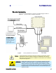


Table Of Contents
- Preface
- Table of Contents
- Reader Overview
- Reader Equipment Installation
- Reader Startup Tool (RST) Software Installation
- Reader Operation
- Reader Startup Tool (RST)
- Embedded Reader Configuration Tool (RCT)
- Configuring Digital Inputs and Outputs
- Specifications
- Reader Specifications (General)
- Reader Specifications (FCC)
- Environmental Specifications
- Power Supply Specifications
- RS-232 Specifications
- Ethernet LAN Specifications
- Antenna Cable Specifications
- External Antenna Specifications (FCC)
- Bulkhead Connector/Interface Cable Pinout
- Battery Specifications (Optional)
- Safety Instructions
- Disposal of the IDentity 5200 Reader
- Reader Maintenance

1
2
3 4 5 6 7 8 9
Reader Equipment Installation
IDentity 5200 User Guide
3
Reader Equipment Installation
Mechanical Installation
The IDentity 5200 is available with two mounting flanges suitable for most
pole and wall mount applications. Any mounting surface must be able to
support a minimum static load of 11.0 pounds (5 kg) plus any additional
live load due to environmental conditions.
Figure 3
IDentity 5200 Mechanical Dimensions and Mounting Hole Locations