
Overview of Primary Product

Step 4
Please refer to page 6-1 for Component Parts List.
Once the fi lter media has been loaded, completely fi ll the media tank with water using a pail or water hose to saturate the
media and expel any air out of the media tank. Some media require a saturation time to prevent washing it from the media
tank to the waste drain upon start-up. Refer to Figure 5, page 2-4 for saturation time. Remove red cap from distributor tube.
Step 5
Secure the control valve onto the media tank; you can use water or a silicone lubricant on the media tank opening, dis-
tributor tube, control valve o-ring and pilot tube o-ring to aid in attaching the control valve to the media tank. Insert the
distributor tube into the pilot tube adapter and slide the control valve down until the valve rests on the fl anged opening of
the media tank. Then with one downward and swift movement push the control valve into the opening of the media tank
to seat the control valve properly. Rocking the control valve to seat on the media tank may roll or pinch the o-ring and will
cause a leak. If pinching or rolling of the o-ring occurs remove the control valve and try again. Be sure to orient the latch
correctly and secure the control valve to the media tank with the clamp assembly as shown in Figure 2.
Step 6
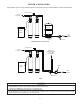
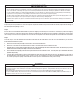
Locate the installation assembly packet and assemble as the enclosed instructions dictate, refer to Figure 3. Attach the
bypass assembly and connection fi tting to the control valve and hand tighten only. Study the instal-
lation drawings provided (Figure 1) to determine the proper location of the Backwash Filtration
System in relation to the other components of the water system (i.e. Water Softener or Water Heater,
if present) and install appropriately.
Step 7
Turn off the power to the well pump on a private well system or close the valve after the water
meter on a public or municipal water system. Depressurize and drain the water lines to allow for
connection of the plumbing to the bypass connection fi ttings on control valve. Be sure to attach the
supply line from the pressure tank or water meter to the INLET side of bypass valve and the service
line connected to the OUTLET side of bypass valve. Leave the bypass valve in the closed position
until instructed later in the installation process.
CAUTION
CAUTION
To reduce the risk associated with property damage due to water leakage:
• Do not apply heat to any fi tting connected to bypass or control valve as damage may result to
internal parts or connecting adapters.
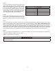
Step 8
The drain line connection can utilize either a 3/4” NPT or a 5/8” COMPRESSION connection. To utilize the 5/8” connection use the provided nut and insert
sleeve with a 5/8” OD rigid or semi-rigid material. Slide the nut over the tubing or piping fi rst, and then insert the sleeve into the piping or tubing until
fl ush. Finally insert piping or tubing in the drain elbow and thread the nut onto the elbow and hand tighten only. To utilize the 3/4” NPT feature for a drain
line connection, remove the 5/8” nut from the elbow and provide your own connection device and pip-
ing for a drain line. Ensure the retaining clip is securely in place before moving on. The discharge end
of the drain line requires an air gap to prevent a cross connection between grey water (sewage) and
potable water (domestic). Refer to Figure 4 to help in the installation.
a. 1/2” ID lengths up to 15 feet and heights lower or slightly higher than the control valve.
b. 5/8” ID length up to 25 feet in length and up to 4 feet above the control valve.
c. For distances higher or longer than previously stated, relocate the CBF Series Residential Back-
wash Filtration System closer to the desired discharge point or consult our Customer Service
Department at 1-866-990-9785 for advice. Avoid overhead drain lines as it may prevent desirable
performance.
Step 9
Connect the transformer to a suitable power supply that is non-switched to plug the transformer into
that meets the local electrical code. The required power source is 110 – 120 volt 60 Hz.
Step 10
Set the time clock for the correct time of day and set the frequency for regeneration appropriately. See “HOW TO SET TIME OF DAY” on page 2-5 for set-
ting the time of day correctly.
Figure 2
Figure 4
OFF
OFF
OFF
OFF
BYPASS
INOUT
CONTROL
VALVE BODY
DRAIN LINE FLOW
CONTROL
ASSEMBLY
Figure 3
2-3