
Operation Manual


UP Plus
3D Printer User Manual
1.
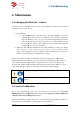
In the UP software, click “3D Print”
menu and click “
Calibrate
2. Click “Reset”
and click
tus bar should then show 0 values as
per picture)
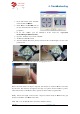
3.
In the UP software open the
files\UP\Example\
Ca
4. Open the “Calibrat
e” box form the “3D Print”
5. 3D Print the
calibration
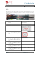
6.
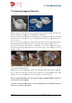
After the calibration model is printed, measure the X1 and X2 length
pictures below.
Then
enter the measured X1 and X2 values into the appr
Remove the Front
Centre ‘L’ shaped component
into the Z box. If it deviates to the right side, the value
value.
If the deviates to the left, the value
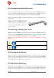
Finally, measure the height of Front
measures near 40mm, enter 40mm as the value.
Click “OK” to record all these v
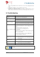
4.
Troubleshooting
3D Printer User Manual
v 2013.6.10
In the UP software, click “3D Print”
Calibrate
”
and click
OK. (the sta-
tus bar should then show 0 values as
In the UP software open the
Calibration model
located in “
Ca
librate96.UP3”
e” box form the “3D Print”
calibration
model.
After the calibration model is printed, measure the X1 and X2 length
, as shown in the
enter the measured X1 and X2 values into the appr
opriate boxes.
Centre ‘L’ shaped component
, and measure its deviation. Put the exact value
into the Z box. If it deviates to the right side, the value
to
be put into the Z box will be a positive
If the deviates to the left, the value
to
put into the Z box will be a negative value.
Finally, measure the height of Front
Center component, which should
be 40mm.
measures near 40mm, enter 40mm as the value.
Click “OK” to record all these v
alues and exit the calibration window.
Troubleshooting
located in “
C:\program
, as shown in the
, and measure its deviation. Put the exact value
be put into the Z box will be a positive
put into the Z box will be a negative value.
be 40mm.
If the part