® SUPERSTACK II™ SWITCH 2000 TR USER GUIDE Version 4.0 http://www.3com.com/ Part No.
3Com Corporation ■ 5400 Bayfront Plaza © 3Com Corporation, 1997. All rights reserved. No part of this documentation may be reproduced in any form or by any means or used to make any derivative work (such as translation, transformation, or adaptation) without permission from 3Com Corporation. 3Com Corporation reserves the right to revise this documentation and to make changes in content from time to time without obligation on the part of 3Com Corporation to provide notification of such revision or change.
CONTENTS Summary of ATM Features 1-10 The FDDI Module 1-10 Benefits of FDDI 1-11 Summary of FDDI Module Features 1-11 The Token Ring-in-Fast Ethernet (TR-in-FE) Module Benefits of TR-in-FE 1-11 Summary of TR-in-FE Module Features 1-12 Migrating to High-speed Technologies 1-13 High-speed Cascade Connectors 1-14 Token Ring Switching Concepts 1-14 Why Token Ring Switching? 1-14 Source Route Bridging (SRT) 1-14 Transparent Bridging (TP) 1-15 Bridge Table 1-15 Source Route Transparent Bridging 1-16 Spanning Tre
Configuration Guidelines 2-3 Power Supply and Fuse 2-3 Replacing the Fuse 2-3 Installing the Slide-in Modules 2-3 Installing the Switch 2000 TR 2-5 Rack Mounting 2-5 Wall Mounting 2-5 Stack Mounting 2-5 Connecting Redundant Power System 2-6 Connecting to the Serial Port 2-6 Connecting a VT100 Terminal 2-6 Device Defaults 2-6 3 SETTING UP FOR MANAGEMENT Switch 2000 TR Management Options 3-1 VT100 Management Interface 3-2 Via the Serial Port 3-2 Via an IP Network Connection 3-2 Configuring Switch 2000 TR in
4 CONFIGURING WITH THE VT100 INTERFACE Quick Setup 4-2 Bridge Configuration 4-3 Setting Source Routing Transparent (VT100) Setting Source Route Bridging 4-4 Setting Transparent Bridging 4-4 Spanning Tree Fields 4-5 Spanning Tree Parameters 4-5 Port Configuration 4-6 Setting Up Ports 4-6 Setting the Port Admin.
5 Unit Configuration 5-1 Bridge Configuration 5-2 Port Configuration 5-3 Setting Port ID 5-3 Viewing Link State 5-3 Setting Port State 5-4 Setting Speed 5-4 Setting Port Personality 5-5 I/O Module Configuration 5-5 6 A VIRTUAL LANS What are VLANs? 7-1 Benefits of VLANs 7-2 How VLANs Ease Change and Movement 7-2 How VLANs Control Broadcast Traffic 7-2 How VLANs Provide Extra Security 7-2 VLANs and the Switch 2000 TR 7-3 The Default VLAN and Moving Ports From the Default VLAN 7-3 Connecting VLANs to a Rou
F TECHNICAL SUPPORT Online Technical Services F-1 World Wide Web Site F-1 3Com Bulletin Board Service F-1 Access by Analog Modem F-1 Access by Digital Modem F-2 3ComFacts Automated Fax Service F-2 3ComForum on CompuServe Online Service Support from Your Network Supplier F-3 Support from 3Com F-3 Returning Products for Repair F-4 3COM CORPORATION LIMITED WARRANTY F-3
ABOUT THIS GUIDE Introduction This guide provides the information you need to install and configure the SuperStack II™ Switch 2000 TR (3C510600) into your Token Ring network for maximum benefit. This guide is intended for use by network administrators responsible for installing and setting up networking equipment. It assumes a basic working knowledge of Local Area Networks and Token Ring in particular.
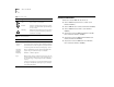
2 ABOUT THIS GUIDE Table 1 Notice Icons Icon Related Publications Type Description Information Note Information notes call attention to important features or instructions. ■ Caution Cautions contain directions that you must follow to avoid immediate system damage or loss of data. Switch 2000 TR Quick Reference Guide. (Part Number #99033) ■ Switch 2000 TR User Guide. (Part Number #99032) ■ Switch 2000 TR Release Notes.
1 OVERVIEW This chapter describes the major features, components, and concepts of the Switch 2000 TR, including: ■ About the SuperStack™ II Switch 2000 TR ■ Summary of Features ■ Typical Applications of Token Ring Switching ■ The Front Panel ■ The Rear Panel ■ Optional Slide-In Modules ■ Token Ring Switching Concepts About the SuperStack™ II Switch 2000 TR The SuperStack II Switch 2000 TR is a multiport internetworking switch for Token Ring networks.
1-2 CHAPTER 1: OVERVIEW ■ Port population—High density port population relieves traffic congestion and supports 4 and 16 Mbps data rates. In addition, the Switch 2000 TR has four custom-configurable ports designed for direct workstation or dedicated server connection. ■ Network management—Switch 2000 TR is supported by the Transcend® Enterprise Manager applications for UNIX and Microsoft Windows 95®.
Summary of Features ■ Roving Analysis—The Roving Analysis Port (RAP) feature allows you to configure the SuperStack II Switch 2000 TR to capture and monitor traffic on any Token Ring LAN connected to the switch using any industry-standard LAN analyzer. This feature operates on Port 1 of the Switch 2000 TR and applies to all ports of the same switch. To view traffic on other switches in a stack you must connect to Port 1 of the appropriate switch and select the port you wish to view.
1-4 CHAPTER 1: OVERVIEW ■ ■ SNMP over IP ■ SNMP MIB II ■ Bridge MIB ■ SR Bridge MIB ■ BOOTP ■ Switch 2000 TR Private (3Com Private) Typical Applications of Token Ring Switching Token Ring switches are best suited for, although not limited to, expanding Token Ring networks. These networks demand high bandwidth, performance, monitoring, management, and a logical migration path for the continued growth of the network while preserving your investment in existing infrastructure.
Ring Segmentation 1-5 Ring Segmentation High-speed switches offer a more efficient solution over 2-port PC bridges or routers. As illustrated below, segmentation with a Token Ring switch brings immediate improvement over existing networks by re-distributing traffic .
1-6 CHAPTER 1: OVERVIEW The Front Panel This section describes the front panel components and LEDs of the SuperStack II Switch 2000 TR. Figure 1-3 shows the front panel.
The Front Panel RJ-45 Ports Table 1-1 12 RJ-45 ports support unshielded Twisted Pair (UTP) or Shielded Twisted Pair cabling (STP) at 4 Mbps or 16 Mbps wire speed. LED Name Power All 12 ports default to adapter mode for connection to a Token Ring hub. Additionally, ports 1 through 4 can be configured to hub mode to allow direct attachment of workstations or servers.
1-8 CHAPTER 1: OVERVIEW The Rear Panel This section describes the rear panel components of the Switch 2000 TR. Figure 1-5 shows the rear panel. Reset IEC Power Socket Serial Number and Fuse Holder Redundant Power System Connector Optional Slide-In Module Slot* Reset Button RS-232 Console Figure 1-5 Switch 2000 TR Rear Panel * Refer to the appropriate module installation manual for more information.
Optional Slide-In Modules Power Socket The Switch 2000 TR automatically adjusts to the supply voltage. The fuse is suitable for both 110 AC and 220-240 AC operation. Refer to “Replacing the Fuse in Chapter 2 for information on replacing fuses. NOTE: The Switch 2000 TR has no ON/OFF switch. Serial Number Refer to this number if you need to report a fault. Redundant Power System Connector Use this connector to attach a Redundant Power System (RPS) to the Switch 2000 TR.
1-10 CHAPTER 1: OVERVIEW to run each of these bandwidth-intensive applications across networks. ■ AAL5 ATM Adaptation Layer ■ 16 Virtual LANs (VLANs) The primary benefits of ATM include: ■ Data buffer to store 40,000 ATM cells ■ Wire Rate Transmission on ATM port ■ Low Latency (68 microseconds between ATM and Token Ring components).
Optional Slide-In Modules Benefits of FDDI Fiber Distributed Data Interface (FDDI) is a 100-Mbps fiber optic local area network standard supported by the ANSI committee. The primary benefits of FDDI include: ■ A 100 Mbps point of aggregation for multiple Token Ring segments. ■ Supports Single Attached Station (SAS) or Dual Attached Station (DAS) functions. ■ Supports server connections via Token Ring FDDI translation of IP, SNA, IPX, and NetBIOS.
1-12 CHAPTER 1: OVERVIEW ■ Manageability ■ Simple to configure and administer TR-in-FE allows both Token Ring and Ethernet to share the same Fast Ethernet physical wiring infrastructure and server base without impacting network performance. TR-in-FE accomplishes this by introducing routing or traditional bridging via Source-Route to Transparent translation. Fast Ethernet is relatively well understood and easy to configure.
Migrating to High-speed Technologies 1-13 Migrating to High-speed Technologies Managers want to migrate to FDDI, ATM, or TR-in-FE easily. Using Switch 2000 TRs, critical resources attach directly to high-speed technologies while preserving the investment in Token Ring hardware. They also merge easily with existing network management applications. These features allow network managers to introduce additional switches, servers, and stations seamlessly via direct connections.
1-14 CHAPTER 1: OVERVIEW High-speed Cascade Connectors These connectors provide a high-speed cascade connection between Switch 2000 TRs in a stack. You can connect multiple units to form a single switched domain. You can connect up to six Switch 2000 TRs with these connectors. A stack of Switch 2000 TRs act as a single multiport switch. The setup configuration parameters are shared among switches and the entire stack can be managed and downloaded as a single IP entity.
Token Ring Switching Concepts the destination ring station. A route is simply the path a packet takes through a source route bridged network from the source ring station to the destination ring station. In a multiple ring environments, nodes on different rings need additional bridging information before they can communicate with each other. A source ring station must first determine if one or more routes exist to another station on a remote ring.
1-16 CHAPTER 1: OVERVIEW table, a switch knows which port must be used to reach each known MAC address. Every time a switch receives a packet, it examines its bridging table to determine if the source MAC address is contained in its bridging table. If it is not, it creates a new entry. The switch then searches its bridging table for the address contained in the packet’s destination address field. The switch then forwards the packet to the port associated with the destination MAC address.
Token Ring Switching Concepts can use any path in the network. ARE packets are flooded through all bridges onto all rings. This creates multiple copies if redundant paths exist in the network. When multiple requests are received at the destination; each one causes a response. Implementing Spanning Tree ensures that the number of broadcast packets are significantly reduced. For more information on Spanning Tree, refer to “Spanning Tree Fields in Chapter 4.
1-18 CHAPTER 1: OVERVIEW Cut-thru mode. The default mode for the Switch 2000 TR is Dynamic Cut-thru. VLANs A VLAN is defined as a group of location- and topology- independent devices that communicate as though they were on the same physical LAN. This means that they are not restricted by the hardware that physically connects them, and segments are defined by flexible user groups created by the user.
2 GETTING STARTED This chapter describes the installation and setup procedures for the Switch 2000 TR: ■ Important Safety Information ■ Positioning the Switch 2000 TR ■ Installing the Slide-in Modules ■ Installing the Switch 2000 TR ■ Connecting Redundant Power System ■ Connecting to the Serial Port ■ Device Defaults Important Safety Information NOTE: Warnings contain directions that you must follow for your personal safety. Follow all instructions carefully.
2-2 CHAPTER 2: GETTING STARTED ■ If the power supply plug is unsuitable and you must replace it, refer to the following specifications: ■ ■ ■ ■ ■ Brown wire to the Live (Line) plug terminal. The terminal may be marked with the letter L or colored red. Blue wire to the Neutral plug terminal. The terminal may be marked with the letter N or colored black. Yellow/green wire to the Ground (earth) plug terminal which may be marked with the letter (E) or the earth symbol or colored yellow/green.
Installing the Slide-in Modules Configuration Guidelines 2-3 Fuse location The cable topology rules for Token Ring are shown below: Media 4 Mbps 16 Mbps Category 3 UTP 660 ft/200m 330 ft/100m Category 4, 5 UTP 1,320 ft/400m 660 ft/200m Type 1 STP 2,000 ft/600m 1,000 ft/300m Power Supply and Fuse The Switch 2000 TR automatically adjusts to the supplied voltage. The fuse is suitable for either 90-110V A.C. or 220-240V A.C. A spare fuse is provided in the fuse drawer.
2-4 CHAPTER 2: GETTING STARTED CAUTION: Always follow Electrostatic Discharge (ESD) procedures when installing an I/O Module. 1 If the Switch is connected to the network, turn off the power and disconnect the switch from the main power supply and the network. 2 Place the Switch on a flat, clean, hard, work surface. 3 Locate and remove the blanking plate that covers the slot. See Figure 2-2. Retain the blanking plate and the screws for future use.
Installing the Switch 2000 TR Installing the Switch 2000 TR Rack Mounting The Switch 2000 TR fits a standard 19-inch data communications rack typically found in wiring closets. 2-5 for mounting the unit. A flat, smooth surface that is dry and sturdy is best. 1 Unpack the Switch 2000 TR and place on a hard, flat surface. 2 Position one of the enclosed mounting brackets over the mounting holes and attach. See Figure 2-4. 1 Unpack the Switch 2000 TR and place it on a hard, flat surface.
2-6 CHAPTER 2: GETTING STARTED Connecting Redundant Power System To install an RPS, proceed as follows: 1 Power down by disconnecting the AC power cord on the Switch 2000 TR. 2 Connect an RPS cable assembly to the RPS connector on the back panel of the Switch 2000 TR. 3 Connect the other end of the RPS cable assembly to the RPS connector on the back panel of the RPS unit.
Device Defaults Speed 16 Mbps Spanning Tree Support Disabled Forwarding Mode Cut-through 802.1d Dynamic Cut-thru Rising Spanning Tree Parameters: 20% Priority 32768 Falling 10% Max Age 20 seconds Broadcast Storm Rising Threshold Hello Time 200 seconds 60% Forward Delay 15 seconds Falling Threshold 50% Rising Action none Falling Action none Port Bridge Defaults Priority 100 Path Cost 62 Attached LAN ID FFFF (hex) Max-Route Desc.
2-8 CHAPTER 2: GETTING STARTED
3 SETTING UP FOR MANAGEMENT This chapter describes background information for configuration and the procedures for initial setup of the SuperStack II Switch 2000 TR, including: ■ Switch 2000 TR Management Options ■ Configuring Switch 2000 TR in Stack ■ Managing over the Network ■ Management Prerequisites ■ Switch 2000 TR Management Consoles ■ Setting Up the VT100 Console ■ Setting Up the LCD Console ■ Setting Up BOOTP ■ Auto Logout ■ Upgrading Software ■ Resetting the Switch 2000 TR
3-2 CHAPTER 3: SETTING UP FOR MANAGEMENT Table 3-1 Switch 2000 TR Management Options Access mechanism Allows you to. . . Using . . . Serial Port IP SNMP LCD Establish an out-of-band connection to the VT100 console.
Configuring Switch 2000 TR in Stack Unit ID # Configuring Switch 2000 TR in Stack SuperStack II Switch 2000 TR LINK STATUS 1x green =link OK yellow =MGMT partition flashing yellow =auto error partition off =inactive 6x Packet — 1 2 3 4 5 6 Status — 1 2 3 4 5 6 Packet — 7x 12x Status — 7 8 7 8 9 10 11 12 O C 9 10 11 12 O C Power MGMT ENTER Option Slot Cascade Head Unit 1x 6x 7x 12x Packet — 1 1 2 3 4 5 6 4 5 6 2 3 Packet — 7 8 Status — 7 8 9 10 11 12 O C
3-4 CHAPTER 3: SETTING UP FOR MANAGEMENT Assigning unique device addresses is the responsibility of your network organization. Managing over the Network Any network manager application running Simple Network Management Protocol (SNMP) can manage the Switch 2000 TR, provided the Management Information Base (MIB) is installed correctly on the management station. SNMP files for all 3Com products are available on the “3Com Bulletin Board Service” in Appendix F.
Management Prerequisites 1-800-444-4345, 1-619-455-4600, 1-703-742-4777 ■ In Europe RIPE NCC Kruislaan 409 NL-1098 SJ Amsterdam The Netherlands Telephone number: 3-5 Management Prerequisites Before you can successfully operate and manage the Switch 2000 TR you must assign a Unit ID number to the device. This section describes the necessary steps for assigning a Unit ID#. The only method for assigning a Unit number is via the LCD Console located on the front panel of the Switch 2000 TR.
3-6 CHAPTER 3: SETTING UP FOR MANAGEMENT Source Routing Prerequisites If you plan to operate the Switch 2000 TR in a source routing environment, you need to assign a segment ID. Follow the instructions below, from the Port Setup screen: 1 Select Bridge from the bottom of the Port Setup screen. Switch 2000 TR Management Consoles The following sections describe how to get started managing your Switch 2000 TR.
Switch 2000 TR Management Consoles [Down Arrow] or [Return] to move to the next field. Refer to “Switch 2000 TR VT100 Console Interface Menu Map”. A list box allows you to select one or more items from a list. These keys allow you to select from a list: ■ [Return]—moves the cursor to the next field. Carries out a button’s action. ■ [Space Bar]—moves through a text list for a field. Use it to highlight the item or value you want.
3-8 CHAPTER 3: SETTING UP FOR MANAGEMENT ■ [Ctrl] + [N]—Moves to the next screen after implementing current screen settings. ■ [Ctrl] + [K]—Displays list of key strokes. Correcting Text Entries Use [Delete] on a VT100 terminal or [Backspace] on a PC. This key moves the cursor one space to the left and deletes a character. To delete more than one character, press the key once for each character. NOTE: Check carefully before using the Control keys.
VT100 Console Menu Map VT100 Console Menu Map Figure 3-4 displays the menu structure for the Switch 2000 TR VT100 console interface.
3-10 CHAPTER 3: SETTING UP FOR MANAGEMENT Setting Up the VT100 Console 4 Log on using the default name security and pass- word security. See Figure 3-6. This section provides instructions for setting up the VT100 console for local or remote management. 1 Connect a VT100-compatible terminal to the serial port of the Switch 2000 TR.
Setting Up the VT100 Console 3-11 Switch 2000 TR Management Setup Fields MAC Address Displays the Switch 2000 TR unit MAC address. Locally Admin Address Figure 3-8 Switch 2000 TR Management Setup Screen 7 Fill in the following fields: ■ Device IP Address ■ Device Subnet Mask (if applicable) ■ Default Router (if applicable) 8 Select OK when you have finished Management Setup. You will be asked to confirm your settings. 9 Press [Enter]. Settings are confirmed.
3-12 CHAPTER 3: SETTING UP FOR MANAGEMENT Work Group ID The workgroup number for purposes of management. Management is only part of a single workgroup and should be viewed as a sub-net. If you move your management setup to a new or different subnet, you will need to change the workgroup ID. Device IP Address You must assign a unique address to the device in this field. You change the IP address using this field. Device SubNet Mask You must assign a suitable network mask to the device in this field.
The LCD Console 3-13 Left Arrow The LCD Console This section describes the LCD Console. The LCD Console allows you to enter specific configuration parameters and obtain status data on the Switch 2000 TR without using a management workstation console or application. Switch 2000 TR Switch 2000 TR Unit Unit Id:Id. 11 Use the left arrow to go to the previous menu. Right Arrow Use the right arrow to move to a specific digit on any data field line.
3-14 CHAPTER 3: SETTING UP FOR MANAGEMENT LCD Console Menu Map Figure 3-10 displays the menu structure for the LCD console interface on the front panel of the Switch 2000 TR. Switch Switch2000 2000TR TR Unit UnitId. Id.
Setting Up the LCD Console Setting Up the LCD Console This section provides instructions for setting up the LCD console for local or remote management. A blank decimal notation appears on the IP Address. 3 Enter IP address as follows: ■ 1 Press the [Enter] button on the front panel LCD to enter the main menu. ■ Switch 2000 TR Switch 2000 TR Unit Unit Id:Id. 11 ENTER Figure 3-11 Front Panel LCD Main Banner 2 Press [Down Arrow] until the Switch 2000 TR >Man- agement screen appears.
3-16 CHAPTER 3: SETTING UP FOR MANAGEMENT 10 Press [Enter]. A blank decimal notation appears in the Default Router field. Setting Up BOOTP The BOOTP option allows you to enable or disable the bootstrap protocol. The BOOTP (bootstrap protocol) allows the switch to discover and learn its own IP address and routing table information. To configure a Switch 2000 TR with the BOOTP option you will need a BOOTP server program.
Setting Up BOOTP Figure 3-12 Stack Setup Screen (BootP Setup) 5 (Optional) Enter a sysname for the stack. 6 Toggle the [Space Bar] to Enable or Disable BootP.
3-18 CHAPTER 3: SETTING UP FOR MANAGEMENT Auto Logout The Switch 2000 TR has a built-in auto logout feature which disables the VT100 interface after approximately three minutes without keyboard activity. This feature provides a level of security for network managers.
Upgrading Software 3-19 Upgrading Software The Software Upgrade feature allows you to download new software images using TFTP running over UDP/IP. When 3Com Corporation issues a new version of the software image for the Switch 2000 TR, you can obtain it from the 3Com Bulletin Board Service. See “3Com Bulletin Board Service in Appendix F. You can download a version of the software image from a single unit in a stack. In most cases this unit will be the head unit.
3-20 CHAPTER 3: SETTING UP FOR MANAGEMENT screen locks. When the download completes, the Switch 2000 TR automatically resets and re-boots with the new software image. 7 In the File Name field, enter “UNIT # n”. Where “n” specifies the unit ID of the unit from which the download occurs. In most cases this unit will be the head unit: Unit # 1.
Resetting the Switch 2000 TR Resetting the Switch 2000 TR 3-21 The Switch 2000 TR resets. This section provides instructions for resetting the Switch 2000 TR. Because some configurable parameters require that you reset the Switch 2000 TR after making changes, it is important to understand the reset procedure before proceeding.
3-22 CHAPTER 3: SETTING UP FOR MANAGEMENT Reset Button The Switch 2000 TR has a reset button on the rear panel of the unit. See Figure 3-16. To reset the Switch 2000 TR using the Reset button, proceed as follows: 1 Locate the Reset button on the rear panel of the Switch 2000 TR. 2 Press the switch once. Power Cord Reset Button The Switch 2000 TR resets. NOTE: The rear panel Reset button also provides access to the Emergency Software Download facility. Press switch twice quickly to view.
4 CONFIGURING WITH THE VT100 INTERFACE The VT100 console is accessed via the serial console and provides access to all configuration, management, and monitoring facilities.
4-2 CHAPTER 4: CONFIGURING WITH THE VT100 INTERFACE Quick Setup The Quick Setup option provides direct access to the Bridge Setup and TR Port Setup screens. 1 Log on to the Switch 2000 TR. The Main Menu appears. See Figure 4-2. Figure 4-3 Quick Config Screen 3 From the Quick Config screen, select either Bridge Setup or TR Port Setup. See the “Bridge Configuration” and “Port Configuration” sections for information about the setup screens.
Bridge Configuration Bridge Configuration The bridge configuration section includes information on the following: ■ Source Routing Transparent (SRT) ■ Source Route (SR) ■ Transparent (TP) ■ Spanning Tree Fields Setting Source Routing Transparent (VT100) NOTE:This bridge setting requires that you reset the switch. Refer to “Resetting the Switch 2000 TR in Chapter 3 for instructions. 1 Log on to the Switch 2000 TR. 2 Select Switch Management from the Main Menu.
4-4 CHAPTER 4: CONFIGURING WITH THE VT100 INTERFACE 13 At the bottom of the TR Port Setup screen, select BRIDGE. The Port Bridge Setup screen appears. See Figure 4-6. 7 Assign a Bridge Number. Enter in Hex from 0 to F. 8 In the Max Age field, type 6. 9 In the Forward Delay field, type 4. 10 Select OK. 11 In the TR Management screen, press [Space Bar] until *Port* appears. Select SETUP. The TR Port Setup screen appears. 12 At the bottom of the TR Port Setup screen, select BRIDGE.
Bridge Configuration 5 In the Spanning Tree field, select *802.1d* to enable ■ 802.1d compliant Spanning Tree for the Switch 2000 TR. The BPDU value is automatically assigned: 80-01-43-00-00-00. Spanning Tree Fields Spanning Tree Parameters The following parameters are components of the Spanning Tree algorithm. These are set to factory defaults. ■ ■ Priority—This setting influences the choice between the root bridge and the designated bridge.
4-6 CHAPTER 4: CONFIGURING WITH THE VT100 INTERFACE Port Configuration The Port configuration section includes directions for configuring ports of the Switch 2000 TR, including: ■ Admin State ■ VLAN ID ■ Port Personality ■ Internal Priority ■ Congestion Control ■ Token Priority ■ Speed ■ Forwarding Mode ■ Cut-Thru Threshold% ■ Locally Administered Address ■ Broadcast Storm Control ■ Port Bridge Settings ■ Spanning Tree Fields NOTE:All settings in the Port Setup screens are “live”
Port Configuration identified by their VLAN ID. All ports are configured by default to VLAN 1. 1 Set this field by entering the desired VLAN number for the current port. 2 Press [Return]. Setting Port Personality Ports 1 through 4 on the Switch 2000 TR can be set to *Adapter* or *Hub*. In “adapter” mode, the port can connect to a token ring hub such as a SuperStack II Hub TR. In “hub” mode, the port acts like a hub port and can support a directly-connected workstation or server.
4-8 CHAPTER 4: CONFIGURING WITH THE VT100 INTERFACE ring ahead in the queue. The frame that has been buffered for the busy or down queue is discarded so that deliverable packets can proceed. ■ ■ Disabled—In the disabled mode, neither Flow Control or Non-blocking are in use. 1 Set this field to one of the aforementioned fields by toggling the [Space Bar]. 2 Press [Return]. Setting Port Speed Speed sets the data rate of ports.
Port Configuration To set a Locally Administered Address, take these steps in the Locally Admin. field: 1 Enter address in hexadecimal. This should be between 400000 000000 and 7FFFFF FFFFFF. 2 Press [OK]. 3 Reset the Switch 2000 TR. NOTE:The Locally Administered address will not be valid until the Switch 2000 TR is reset. Refer to “Resetting the Switch 2000 TR in Chapter 3 for instructions on resetting.
4-10 CHAPTER 4: CONFIGURING WITH THE VT100 INTERFACE Port Bridge Configuration ■ Set the Spanning Tree and Source Routing fields for the Port using the Bridge selection, located at the bottom of the Port Setup screen. Choices are: ■ Priority ■ Path Cost ■ Attached LAN ID ■ Max. Route-Desc ■ STE Mode From the Port Setup screen, perform these steps. 1 Select *Bridge* from the lower portion of the Port Setup screen.
I/O Module Configuration ■ ■ Forced— Indicates that the port will always accept and propagate STE packets. Auto-Span—Indicates that the port will accept and propagate STE packets when its Spanning Tree state is forwarding. NOTE:Spanning Tree does not have to be enabled for this to function correctly. 4 Select OK to save changes.
4-12 CHAPTER 4: CONFIGURING WITH THE VT100 INTERFACE Setting sysName The sysName field allows you to assign an identifying name to the stack. This name is displayed on the top level form. 1 Enter any combination of up to 30 alpha or numeric characters as an identifier. Spaces are allowed. 2 Select OK. BOOTP Client If BOOTP Client is enabled and you have a BootP server on your network, an IP address will be assigned automatically to the Switch 2000 TR at power up.
VLAN Configuration ■ ■ ATM—The port is an ATM OC-3c Module port. For more information, see the SuperStack II Switch ATM OC-3c Module User Guide. VLAN Membership—This field displays the ID of the VLAN(s) to which the port belongs. ■ ■ Port ID—This field displays the ID of the port currently selected in the listbox. VLAN ID—This field allows you to enter the ID of the VLAN to which the port is assigned. All ports by default belong to VLAN 1.
4-14 CHAPTER 4: CONFIGURING WITH THE VT100 INTERFACE Unit Configuration Unit configuration allows you to view these unit parameters: ■ Unit ID ■ Unit Name ■ Port Capacity ■ Option Slot ■ Power Supply For more information on the unit, refer to “Unit Statistics in Chapter 6. Setting Up the Unit 1 Log on to the Switch 2000 TR. 2 Select Switch Management from the Main Menu. 3 Press [Space Bar] and select *Unit*. 4 Enter the ID of the unit you wish to set up. 5 Select SETUP.
Administrative Configuration Power On Self Test Use this field to specify the type of self-test to run at start-up: ■ Normal—A 10 second test that verifies the Switch 2000 TR’s basic functions. ■ Extended—A more comprehensive test that lasts up to 300 seconds. 4-15 Administrative Configuration This section provides information on the Administrative settings for the Switch 2000 TR. 1 Log on and select USER ACCESS LEVELS from the Main Menu. The TR User Access Levels menu appears. See Figure 4-12.
4-16 CHAPTER 4: CONFIGURING WITH THE VT100 INTERFACE ■ EDIT USER—Allows you to change your password and community. You cannot change other passwords or community strings. 2 Select the menu item you want and see the appropri- ate description and instructions on the following pages. Setting Local Security The TR Local Security screen displays a matrix of access options for security levels. Choices: ■ Monitor—Allows read-only access to a restricted set of manageable parameters.
Administrative Configuration 3 Select OK when you are finished filling in the fields. Creating New Users Follow these steps to create new users and assign access levels to the Switch 2000 TR. 4-17 characters and are case-sensitive. Passwords are not displayed on screen. 3 Assign access levels according to these descriptions and your network needs. Toggle the [Space Bar] to view the levels. ■ From the TR USER ACCESS LEVELS screen: 1 Select CREATE USER. The TR Create User screen appears.
4-18 CHAPTER 4: CONFIGURING WITH THE VT100 INTERFACE 2 Scroll using the [Down Arrow] until you highlight the ■ User Name—This read-only field displays the name of the user. This field cannot be changed using this screen. To change the name of the user, delete the user and create a new name. ■ Old Password—Enter the old password for this user. ■ New Password—Enter the new password for this user. ■ Confirm Password—Re-enter the new password for verification.
About the Switch Database (SDB) time (aging time). This practice prevents the database from filling with obsolete entries. When a device is removed from the network, its entry is deleted from the database. Using an SNMP-based management application or the VT100 console (serial port or Telnet session), you can set the aging time (set in seconds) with a default of 5 minutes. Aging entries are deleted if the Switch 2000 TR is reset or turned off.
4-20 CHAPTER 4: CONFIGURING WITH THE VT100 INTERFACE Switch Database Configuration The Switch 2000 TR Unit Database View screen allows you to set up, maintain, and view the database. The Switching Database is distributed across the units in a stack. You need to choose a unit before you can observe the addresses learned by that unit.
SNMP Trap Configuration ■ REFRESH—Command allows you to refresh the database and display the latest address entries. ■ INSERT—Command allows you to add an entry to the database. ■ DELETE—Command allows you to remove an entry from the database. 4-21 Finding Entries in the Database From the Unit Database View screen, proceed as follows: 1 Enter the MAC address of the device you wish to find in the MAC Address field. 2 Select FIND. The entry appears highlighted in the list box.
4-22 CHAPTER 4: CONFIGURING WITH THE VT100 INTERFACE Serial Port Configuration The VT100 interface provides a screen for setting the parameters of the serial port of the Switch 2000 TR. The serial port provides out-of-band communications with the Switch 2000 TR for purposes of local configuration and communication. To view the Switch 2000 TR Serial Port Setup screen, proceed as follows, from the Switch 2000 TR Main Menu banner. Figure 4-19 TR Trap Setup Screen 1 Select Management Setup.
Serial Port Configuration 4-23 minal’s serial port parameters match those on the Switch 2000 TR. This allows you to continue to access the management facility from the equipment after you change the serial port parameters. modem. Refer to your terminal or modem documentation for more information. The Serial Port Setup screen displays the following: Enabled/Disabled The Switch 2000 TR can auto-configure the line speed (baud) to work with your VT100-compatible terminal.
4-24 CHAPTER 4: CONFIGURING WITH THE VT100 INTERFACE Initializing the Switch 2000 TR The Switch 2000 TR VT100 interface allows you to initialize the nonvolatile memory on the unit and return to the factory defaults. Be aware that all configuration parameters, database entries, and setting will be erased and returned to the original factory-set defaults. You should only initialize the Switch 2000 TR if: ■ The current configuration scheme no longer suits your network.
5 CONFIGURING WITH THE LCD CONSOLE This chapter describes the Switch 2000 TR LCD Console management facilities and provides procedures for configuring and managing the device. This console is accessed from the front panel and provides access to most configuration, management, and monitoring facilities. This chapter assumes you have prepared the Switch 2000 TR for management.
5-2 CHAPTER 5: CONFIGURING WITH THE LCD CONSOLE Bridge Configuration Bridge settings can be made using the LCD console. If you have made settings using the VT100 interface, those settings will be reflected in the LCD console. Refer to Chapter 3 for more information on navigating the LCD console. ■ Transparent Bridging ■ Source Route 6 Press [Enter] to select appropriate bridge type. BRIDGE >Bridge Type appears. 7 Press [Down Arrow]. BRIDGE >Spanning Tree appears.
Port Configuration 5-3 Setting Port ID Port Configuration Port parameters can also be set from the LCD console on the Switch 2000 TR front panel. If you have made settings using the VT100 interface, those settings will be reflected in the LCD console. Refer to Chapter 3 for more information on navigating the LCD console and the LCD console map. The screens are circular, meaning that you can access them by scrolling either up or down.
5-4 CHAPTER 5: CONFIGURING WITH THE LCD CONSOLE 4 Press [Down Arrow] until Port # >Link State appears. 5 Press [Enter]. Link State # >[state] appears. The Link State identifies the current state of the port you are viewing. ■ Disabled ■ Blocking ■ Listening ■ Learning ■ Forwarding ■ Broken This read-only field cannot be changed. 6 Press [Left Arrow] to return to previous menu. Setting Port State From the Switch 2000 TR>Unit Id # LCD banner, proceed as follows: 1 Press [Enter].
I/O Module Configuration Setting Port Personality Ports 1 through 4 can each be configured as either “Hub Port” or “Adapter Port.” The Adapter mode is the default for these ports. Ports 5 through 12 can only be set as “Adapter Port.” Refer to “SuperStack II Switch 2000 TR Front Panel RJ-45 Ports in Chapter 1 for more information. From the Switch 2000 TR>Unit Id # LCD banner, proceed as follows: 1 Press [Enter]. Switch 2000 TR >Unit appears. 2 Press [Down Arrow] until Switch 2000 TR >Port appears.
5-6 CHAPTER 5: CONFIGURING WITH THE LCD CONSOLE Switch 2000 TR > I/O Module ENTER Module Type Module State HW Version SW Version Boot SW Ver For more information about setting up the modules refer to the documentation that came with them: ENTER ■ SuperStack II Switch 2000 TR ATM OC-3 Module User Guide (Part Number #99041) ■ SuperStack II Switch 2000 TR FDDI Module User Guide (Part Number #99048) ■ SuperStack II Switch 2000 TR TR-in-FE Module User Guide (Part Number #99045) L Figure 5-2 I/O Modul
MONITORING THE SWITCH 2000 TR 6 This chapter provides information on viewing the current operating status of the Switch 2000 TR, displaying errors using the fault log, and carrying out a remote poll (PING). Regularly viewing statistics allows you to be sure that your network and Switch 2000 TR devices are operating properly.
6-2 CHAPTER 6: MONITORING THE SWITCH 2000 TR Unit Statistics NOTE:The Unit Statistics screen provides an easy method for viewing per-port performance. It displays port traffic activity for each active port. Values are refreshed approximately every two seconds. The counters are reset after the values reach approximately 4.2 billion. See Figure 6-2. To view the Unit Statistics screen, take these steps from the Switch 2000 TR Main Menu: 1 Select Switch Management. The TR Management screen appears.
Port Statistics Port Statistics The TR Port Statistics screen provides an easy method for viewing individual port performance. See Figure 6-3. TR Port Statistics provide more detailed information on individual ports. This screen also provides access to the Traffic Statistics screen. To view the TR Port Statistics screen, take these steps from the Switch 2000 TR Main Menu: The TR Port Statistics screen displays this information: Unit ID—The number of the unit with which the port is associated.
6-4 CHAPTER 6: MONITORING THE SWITCH 2000 TR Current Utilization—The percentage of bandwidth usage for the port you are currently viewing. This value indicates the general traffic level on the individual port. Ideally, this figure should be below 60%, which indicates that the port is responsible for a reasonable amount of traffic relative to the entire ring. ing. A typical TR Port Statistics (Traffic) screen appears in Figure 6-4.
Port Statistics directed to a broadcast address or frames received with errors. Broadcasts Received—The number of frames received that have a broadcast destination address. This number does not include frames with errors. Octets Received—The number of octets received by the port, including the MAC header and CRC. Octet counters are accurate to the nearest 256-byte boundary. Octets Transmitted—The number of octets transmitted by the port, including the MAC header and CRC.
6-6 CHAPTER 6: MONITORING THE SWITCH 2000 TR Stack Status The Stack Status screen provides easy access to the vital statistics associated with a stack. Units and their status, the software version currently running on each unit and the MAC address of each unit displays. To view the Stack Status screen, perform these steps using the Switch 2000 TR Main Menu: 1 Select Switch Management. The TR Management Screen appears. 2 Press [Space Bar] until Stack appears.
Status Status The Status screen provides read-only information about the Switch 2000 TR. Information provided on this screen is especially useful for troubleshooting and monitoring system history. You can view some Status information using the LCD console on the front panel of the Switch 2000 TR. Refer to “LCD Status” for more information. To view the Status screen, perform these steps using the Switch 2000 TR Main Menu: 1 Select STATUS and press [Return].
6-8 CHAPTER 6: MONITORING THE SWITCH 2000 TR Fault Log The Fault Log displays read-only information about the Switch 2000 TR. The Fault Log updates whenever an abnormal condition occurs. This information is for internal 3Com use only. Your supplier may ask you to quote the Area and Fault Number if you report a problem. To view the Fault Log, take these steps from the Switch 2000 TR Main Menu: 1 Select STATUS and press [Return]. The TR Status screen appears. 2 Select FAULT LOG and press [Return].
Remote Polling (PING) Remote Polling (PING) The Remote Poll screen allows you to send a single frame to a remote device. Use this feature to verify if a remote device is active and responding. It can help locate network problems and is also referred to as PING. To use the Remote Poll feature, take these steps from the Switch 2000 TR Main Men: 1 From the Switch 2000 TR Main Menu, select Remote Poll. The TR Remote Poll screen appears.
6-10 CHAPTER 6: MONITORING THE SWITCH 2000 TR 5 Press [Down Arrow]. LCD Status The LCD console located on the front panel of the Switch 2000 TR provides useful hardware, software, and system version information. Refer to Chapter 5 for more information. Switch 2000 TR > Status STATUS >SW Version> appears. 6 Press [Enter]. SW Version #> appears and displays the Boot software version stored on the Switch 2000 TR. 7 Press [Left Arrow] to return to STATUS > SW Version>.
7 VIRTUAL LANS This chapter provides information on Virtual Local Area Networks (VLANs). Definitions, benefits, sample configurations and concepts of VLANs are described here, including: ■ What are VLANs? ■ Benefits of VLANs ■ VLANs and the Switch 2000 TR Setting up Virtual Local Area Networks (VLANs) on the Switch 2000 TR provides you with less time-consuming network administration and more efficient network operation.
7-2 CHAPTER 7: VIRTUAL LANS Benefits of VLANs Implementing VLANs on your network has three main advantages: ■ It eases the change and movement of devices on networks. ■ It helps to control broadcast traffic. ■ It provides extra security. How VLANs Ease Change and Movement With traditional IP networks, network administrators spend much of their time dealing with moves and changes. If users move to a different IP subnet, the IP addresses of each endstation must be updated manually.
VLANs and the Switch 2000 TR VLANs and the Switch 2000 TR Backbone Connecting Multiple Switches Switch A 1 2 Switch B 3 4 5 6 7 8 9 10 11 12 1 2 3 4 5 Figure 7-1 The concept of VLANs 6 7 8 9 10 11 12 The Switch 2000 TR supports VLANs which consist of a set of switch ports. Each switch port can only belong to one VLAN at a time, regardless of the device to which it is attached. Each Switch 2000 TR can support up to 16 VLANs.
7-4 CHAPTER 7: VIRTUAL LANS Connecting Common VLANs Between Switch Units In the Switch 2000 TR, you typically connect VLANs to other Switch 2000 TRs and units using backbone ports. This allows the Switch to forward all frames with an unknown address to the rest of the network, and it also stops the Switch Database from becoming full if there are more than 500 addresses in the network. Note that you normally require one backbone port per VLAN.
VLANs and the Switch 2000 TR Switch 2000 TR VLAN 1 VLAN 2 Connection for VLAN 1 Connection for VLAN 2 Router Figure 7-2 VLAN configuration with a single Switch 2000 TR unit 7-5
7-6 CHAPTER 7: VIRTUAL LANS
A SOFTWARE UPGRADE UTILITY The SuperStack II Switch 2000 TR has a back-up Software Upgrade Utility that allows you to: ■ ■ Software Upgrade Utility Command Set Download a new software image if the operational image has been damaged. This feature should be used for emergency situations only! At the > prompt you can enter commands followed by a [Return]. The commands are not case-sensitive. Download a new software image for new revisions. Sets the IP address of the Switch 2000 TR.
A-2 APPENDIX A: SOFTWARE UPGRADE UTILITY L Lists the current settings of the Switch 2000 TR and provides a status report for the previous download attempts. Use this command to check that you have entered all the parameters necessary for a successful download. Figure A-1 represents the screen after using the command. M (subnet mask) Enter the subnet mask in dotted decimal format. For Example: 255.255.0.
Using the Commands Using the Commands The following sections tell you how to use the Software Upgrade Utility screen. If you enter the Software Upgrade Utility accidentally, enter the command G to quit. If you give no keyboard input for 30 seconds, the utility will time out. A-3 The utility displays a series of dots on the screen as the download proceeds. After approximately two minutes, this message appears: Software Upgrade Complete 3 Reset the device.
A-4 APPENDIX A: SOFTWARE UPGRADE UTILITY 11—Invalid record type. Status Messages The Software Upgrade utility reports the status of the last download attempt. It reports error messages if the download was unsuccessful. 12—Checksum error. Message 13 and 14 indicate that you are trying to load the wrong type of software image file. The status messages are described below: 13—File is for the wrong device type. Messages 1 through 7 are standard TFTP errors as detailed in IFC 783.
B SCREEN ACCESS RIGHTS The table in this appendix specifies which level of users can view and usually edit (write). Access rights allow users to view and/or edit the Switch 2000 TR VT100 management screens. Screen Accessible to . . . Port Statistics (Error) Monitor Manager Security All access rights are read-and-write except where noted as read-only.
B-2 APPENDIX B: SCREEN ACCESS RIGHTS Screen Accessible to . . .
C SERIAL PORT CABLE PIN-OUTS ■ SuperStack II Switch 2000 TR ATM OC-3 Module User Guide (Part Number #99041) ■ SuperStack II Switch 2000 TR FDDI Module User Guide (Part Number #99048) ■ SuperStack II Switch 2000 TR TR-in-FE Module User Guide (Part Number #99045) Null Modem Cable 9 pin to RS-232 25 pin. Pin numbers that are underlined are different. All other pin designations are straight through.
C-2 APPENDIX C: SERIAL PORT CABLE PIN-OUTS
D TROUBLESHOOTING The SNMP manager cannot access the device: Troubleshooting Procedures This appendix lists potential problems you might see when managing the Switch 2000 TR and includes suggested actions to take. If you experience a problem not listed here or that you cannot solve, please contact your local technical support representative. The initial Main Banner screen does not display: Check that your terminal or terminal emulator is correctly configured to operate as a VT100 terminal.
D-2 APPENDIX D: TROUBLESHOOTING The SNMP manager or Telnet workstation can no longer access the device: If Power LED is Yellow. . . Unit failed self-test. Return to supplier. Check that Remote Telnet access or Community-SNMP access is enabled. If port fails to join ring . . . Check that the port through which you are accessing the device has not been disabled, see "Port Configuration" in Chapter 4. If it is enabled, check the connections and network cabling at the port. Check ring speed and cable.
E SWITCH 2000 TR TECHNICAL SPECIFICATIONS Physical Dimensions Height: 2.75 inches (7.0 cm) x Width: 17.25 inches (44cm) x Depth 12 inches (30.5 cm) Weight: 4.4kg (9.7lbs) Environmental Requirements Operating Temperature 32˚ to 120˚F (0˚ to 50˚ C) Operating Humidity 10 to 95% relative humidity, non-condensing Safety Agency Certifications UL 1950, EN60950 (TUV), CSA 22.2 No.
E-2 APPENDIX E: SWITCH 2000 TR TECHNICAL SPECIFICATIONS Specifications for Module Options If you have an ATM, FDDI, or TR-in-FE module, see the following manuals for technical specifications: ■ SuperStack II Switch 2000 TR ATM OC-3 Module User Guide (Part Number #99041) ■ SuperStack II Switch 2000 TR FDDI Module User Guide (Part Number #99048) ■ SuperStack II Switch 2000 TR TR-in-FE Module User Guide (Part Number #99045)
F TECHNICAL SUPPORT and support, news about the company, Net Age® Magazine, and more. 3Com provides easy access to technical support information through a variety of services. This appendix describes these services. Information contained in this appendix is correct at time of publication. For the very latest, we recommend that you access 3Com Corporation’s World Wide Web site.
F-2 APPENDIX F: TECHNICAL SUPPORT Country Data Rate Telephone Number Taiwan, R.O.C. up to 14400 bps 886 2 377 5840 U.K. up to 28800 bps 44 1442 438278 U.S.A. up to 28800 bps 1 408 980 8204 Access by Digital Modem ISDN users can dial in to 3ComBBS using a digital modem for fast access up to 56 Kbps.
Support from Your Network Supplier 3ComForum on CompuServe Online Service 3ComForum contains patches, software, drivers, and technical articles about all 3Com products, as well as a messaging section for peer support. To use 3ComForum, you need a CompuServe account. To use 3ComForum: 1 Log on to your CompuServe account. F-3 Support from 3Com If you are unable to receive support from your network supplier, technical support contracts are available from 3Com.
F-4 APPENDIX F: TECHNICAL SUPPORT Regional Sales Office Telephone Number 3Com Canada Calgary Edmonton Montreal Ottawa Toronto Vancouver 403 265 3266 403 423 3266 514 683 3266 1 613 566 7055 416 498 3266 604 434 3266 3Com France 33 1 69 86 68 00 3Com GmbH Austria Czech Republic/Slovak Republic Germany (Central European HQ) Hungary Poland Switzerland 43 1 513 4323 420 2 21845 800 49 30 34 98790 (Berlin) 49 89 627320 (Munich) 36 1 250 83 41 48 22 6451351 41 31 996 14 14 3Com Iberia Portugal Spain 35
1 INDEX Numbers 3Com Bulletin Board Service (3ComBBS) F-1 3Com sales offices F-3 3Com URL F-1 3ComFacts F-2 3ComForum F-3 A Administrative Settings CREATE NEW USER 4-15 DELETE USERS 4-15 EDIT USER 4-16 LOCAL SECURITY 4-15 ATM networks extending VLANs into 7-4 Auto 3-18 Auto Logout, description of 3-18 B backbone port 4-12, 7-4 specifying 4-13 Blocking, description of 6-3 BootP Client 4-12 BOOTP, setting up 3-16 Bridge Configuration Source Routing Transparent (VT100) 4-3 Bridge Configuration (LCD Console)
2 L LCD Console 3-15 LCD Display Buttons description of 1-7 LCD Statistics 6-10 Learning, description of 6-3 Link State viewing LCD Console 5-3 Listening, definition of 6-3 Local Security Community SNMP 4-16 Manager 4-16 Monitor 4-16 Remote Telnet 4-16 Secure Monitor 4-16 Security 4-16 Serial Port 4-16 Setting 4-16 Specialist 4-16 Locally Admin Address, management set up 3-11 M Management Prerequisites, initial set up 3-5 Management Setup Fields Locally Admin.
3 Reset Button Reset 3-22 VT100 Reset 3-21 returning products for repair F-4 RJ-45 Ports, description of 1-6 Roving Analysis, description of 1-3 S Safety Information 2-1 Screen Access Rights B-1 screens VLAN Setup 4-12 Serial Port connecting to 2-6 setting Auto Config 4-23 Char Size 4-23 Connection Type 4-23 DCD Control 4-23 DSR Control 4-23 Flow Control 4-23 Parity 4-23 Speed 4-23 Serial Port Cable Pin-outs C-1 Serial Port, setting Stop Bit 4-23 Slide-in Module Slot, description of 1-9 Slide-in Option Sl
4 V Virtual LAN Trunks.
3Com Corporation LIMITED WARRANTY The duration of the warranty for the SuperStack II Switch 2000 TR, is n years.
warranty gives you specific legal rights which may vary depending on local law.