Using the SuperStack II NETBuilder SI Bridge/Router ® ® ® http://www.3com.com/ Part No.
3Com Corporation 5400 Bayfront Plaza Santa Clara, California 95052-8145 Copyright © 3Com Corporation, 1998. All rights reserved. No part of this documentation may be reproduced in any form or by any means or used to make any derivative work (such as translation, transformation, or adaptation) without permission from 3Com Corporation.
Shielded Cables Connections between 3Com equipment and other equipment and peripherals must be made using shielded cables in order to maintain compliance with FCC, and other agency, electromagnetic frequency emissions limits. This statement does not apply to the ISDN cable or 10BASE-T cables. Federal Communications Commission Notice This equipment has been tested and found to comply with the limits for a Class B digital device, pursuant to Part 15 of the FCC rules.
Canadian Certification Notice The Industry Canada label identifies certified equipment. This certification means that the equipment meets certain telecommunications network protective, operational, and safety requirements. The Department does not guarantee the equipment will operate to the users’ satisfaction. Before installing this equipment, users should ensure that it is permissible to be connected to the facilities of the local telecommunications company.
CE Notice Marking by the symbol indicates compliance of this equipment with the EMC, Telecom and Low Voltage Directives of the European Community. Such marking is indicative that this equipment meets or exceeds the following technical standards: EN55022 — Limits and methods of measurement of radio interference characteristics of information technology equipment. EN50082-1 — Electromagnetic compatibility - generic immunity standard part 1: residential, commercial, and light industrial.
CONTENTS ABOUT THIS GUIDE Conventions 15 Year 2000 Compliance 1 16 FEATURES AND SPECIFICATIONS Features 17 Back and Front Panels 18 DIP Switches 20 Hardware Interrupt Switch 20 Reset Button 21 Serial Device Requirements 21 2 USING THE BRIDGE/ROUTER IN YOUR NETWORK Overview 23 Using Ethernet LAN Ports 23 Using WAN and Serial Ports 24 ISDN Port (Model 43x, 53x, 44x and 54x) 24 56/64K CSU/DSU Port (Model 45x and 55x) 24 T1/FT1 CSU/DSU Port (Model 46x and 56x) 24 Serial Ports 25 Telco Services 25 Using PPP
Mounting Kit 31 Installing on a Tabletop 31 Stacking with Brackets 32 Installing in a Rack 33 Cabling the Connectors 34 Cabling the LAN Connectors 34 Cabling the WAN Connector 35 Model 43x and 53x ISDN S/T 35 Model 44x and 54x ISDN U 35 Model 45x and 54x 56/64K CSU/DSU Model 46x and 56x T1/FT1 36 Cabling the Serial Connectors 37 Attaching a Redundant Power System 38 Connecting a PC, Terminal, or Modem 39 Shutting Down 39 4 INSTALLING OR REMOVING AN INTERFACE MODULE Removing the Cover 41 Removing an Existi
Setting Up Security 6 62 BASIC CONFIGURATION OF PORTS AND PATHS Paths, Ports, and Virtual Ports 63 Paths and Ports 63 Dynamic Paths 64 Multiple Static Paths per Port 65 Virtual Ports 65 Virtual Ports over Frame Relay and X.25 66 Virtual Ports over PPP 67 Parent Ports for Frame Relay and X.25 68 Path and Port Numbering 69 Configuring Ethernet Paths and Ports 70 Configuring ISDN on the WAN Port (43x, 44x, 53x, and 54x) 70 Configuring ISDN in the U.S.
Using Manual Dial 90 Configuring Bandwidth-On-Demand 91 Configuring Disaster Recovery 92 Configuring Frame Relay 93 Scenario 1: Multiple Destinations, Nonmeshed Scenario 2: Partially Meshed Topology 95 Scenario 3: Fully Meshed Topology 97 Configuring X.
9 CUSTOMIZING YOUR SOFTWARE Naming Paths and Ports 111 Path and Port Naming Restrictions 111 Using the 56/64 Kbps CSU/DSU Module Autobaud Feature 112 Prerequisites 112 Defaults 112 Procedure 112 Working with Dial Number Lists 113 Adding a Phone Number 113 Redialing When the Connection Fails 113 Dialing the Same Phone Number Multiple Times 113 Positioning a Phone Number 114 Editing an Existing Phone Number 114 Deleting a Phone Number 114 Using Statistics on the 56/64 Kbps CSU/DSU Port (45x and 55x) 115 Usin
Serial LEDs 124 WAN LEDs 125 LAN LEDs 125 Error LED Meanings 126 Troubleshooting During the Load Phase 126 Troubleshooting During the Test Phase 131 Errors Indicated by the Serial LEDs 131 Errors Indicated by the WAN LEDs 132 Performing Loopback Tests 133 Response to Local Loopback Assertion 133 Performing a Loopback Test on the ISDN Port (43x, 53x, 44x and 54x) 133 Prerequisites 133 Performing a V.
C SYNTAX CONVENTIONS Full Form Syntax 153 Abbreviated Syntax 154 Symbols 154 Full and Abbreviated Syntax Examples 155 Variations in Command Syntax 156 Entering Service Names in Command Lines 157 Using Aliases 157 Command History Substitution 158 Privilege Level 159 ISDN-Related Syntax Variation (Models 43x and 44x) 159 Getting Help 160 D CONNECTORS AND CABLES Console Connector and Cables 163 PC Cable 163 Terminal Cable 164 Modem Cable 164 LAN Connector and Cables 165 10BASE-T Cabling 165 Cabling Standard
RS-530 DTE Cable Pinouts E 185 PROVISIONING YOUR ISDN LINE Ordering U.S.
ABOUT THIS GUIDE This guide includes basic software configuration information for the the SuperStack® II NETBuilder® SI bridge/router: For more information about configuring the software, see Using Enterprise OS Software. This guide is intended for experienced system integrators and network administrators. If release notes are shipped with your product and the information there differs from the information in this guide, follow the instructions in the release notes.
ABOUT THIS GUIDE Table 2 Text Conventions Convention Description Screen displays This typeface represents information as it appears on the screen. Syntax Evaluate the syntax provided and supply the appropriate values. Placeholders for values you must supply appear in angle brackets. Example: Enable RIPIP using: SETDefault ! -RIPIP CONTrol = Listen In this example, you must supply a port number for . Commands Enter the command exactly as shown in text and press the Return or Enter key.
1 FEATURES AND SPECIFICATIONS This chapter provides an overview of the SuperStack II NETBuilder SI bridge/router and includes the following information: Features ■ Features ■ Back and Front Panels ■ DIP Switches ■ Hardware Interrupt Switch ■ Serial Device Requirements Table 3 lists features of the SuperStack II NETBuilder SI bridge/router. Table 3 Features of the SuperStack II NETBuilder SI Bridge/Router Feature Description Processor Motorola 68360 28.
CHAPTER 1: FEATURES AND SPECIFICATIONS Table 3 Features of the SuperStack II NETBuilder SI Bridge/Router (continued) Feature Description Serial ports Two (model 4xx) or four (model 5xx) Flex-WAN serial ports that can connect to RS-232, V.35, RS-449, X.21, or RS-530 interfaces. See “Serial Connectors and Flex-WAN Cables” on page 174 for information about Flex-WAN cables. Boundary routers (model 4xx only) Back and Front Panels One active serial or WAN port.
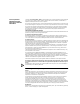
L1 L1 L2 Fault Active Link 100mb L1 L2 Fault Active Link 100Mb A B1 B2 Fault Connect Link SERIAL D Link, Active, and Fault LEDs (A, B, C, and D) C A D B Fault Active Link Reset Fault Active Link Fwd Power/ Fault Aux Link, Connect, and Fault LEDs (CSU/DSU B1 and B2) Fwd Test Power /Fault Load Run Run, Load, and Test LEDs Status LEDs SYSTEM Status SuperStack II NETBuilder Console ® ® Fwd and Power/ Fault LED Aux and Power/ Fwd Fault LED LEDs Test Load Run Run, L
CHAPTER 1: FEATURES AND SPECIFICATIONS DIP Switches DIP switches are located on the left side of the bridge/router (when facing the front panel) and are for 3Com use only. CAUTION: To avoid accidentally erasing your flash memory or reinitializing the EEPROM, make sure all switches are in the down position. Left side of unit DIP switches Hardware Interrupt Switch The hardware interrupt switch is located on the left side of the bridge/router (when facing the front panel).
Reset Button Reset Button 21 Pressing the Reset button resets the bridge/router. The reset button on the model 4xx bridge/router is on the front panel as shown in Figure 2. The reset button on the model 5xx bridge/router is on the left side of the bridge/router (when facing the front panel) as shown in Figure 3. Figure 3 Reset Switch (Model 5xx) Left side of unit Reset switch Serial Device Requirements Serial devices using the V.
CHAPTER 1: FEATURES AND SPECIFICATIONS
2 USING THE BRIDGE/ROUTER IN YOUR NETWORK This chapter gives an overview of SuperStack II NETBuilder SI bridge/routers and describes how they fit in your network. It also describes the software features of the bridge/router. Overview SuperStack II bridge/routers maintain connectivity among small, midsize, and large branch offices and the corporate LAN.
CHAPTER 2: USING THE BRIDGE/ROUTER IN YOUR NETWORK Using WAN and Serial Ports SuperStack II NETBuilder SI bridge/routers come with two or four serial ports and one of the following WAN ports: a built-in ISDN S/T terminal adapter (TA) (models 43x and 53x), a built-in ISDN U TA (models 44x and 54x), a built-in 56/64 Kbps CSU/DSU (models 45x and 55x) or a built-in T1/FT1 Telco port (models 46x and 56x). ISDN Port (Model 43x, 53x, 44x and 54x) The ISDN port provides a basic rate interface (BRI).
Telco Services Serial Ports 25 The serial ports are multifunction Flex-WAN ports that provide connection to industry-standard V.35, RS-232, RS-449, RS-530, or X.21 Data Communications Equipment (DCE) or Data Terminal Equipment (DTE) serial devices. You can buy Flex-WAN cables separately from 3Com. See Appendix D for more information about Flex-WAN cables.
CHAPTER 2: USING THE BRIDGE/ROUTER IN YOUR NETWORK Table 4 Dial-Up and Leased Line Services Protocol Serial Device (Required on Flex-WAN Serial Ports) Data Transfer Rate PPP CSU/DSU Up to 24 channels (DS0s) at 64 Kbps each Digital Data Service (DDS) PPP CSU/DSU Up to 64 Kbps Telco Line Fractional T1 * Some ISDN lines support up to 56 Kbps per B channel. For more information, contact your ISDN service provider.
Telco Services 27 defines a point-to-point interaction between DTEs and DCEs. In simpler terms, when it is time to transmit data, a terminal connects to a modem or packet switch, which then connects to packet switching exchanges (PSEs) and other DCEs to transmit the data to its final destination at another terminal. The links by which data is transmitted are called virtual circuits. Virtual circuits allow data transfers between two points on the network through any number of nodes in the network.
CHAPTER 2: USING THE BRIDGE/ROUTER IN YOUR NETWORK
3 INSTALLING THE HARDWARE This chapter describes how to install your SuperStack II NETBuilder SI bridge/router. Required Equipment Table 6 lists the items you receive in the shipping carton and items you need to provide.
CHAPTER 3: INSTALLING THE HARDWARE For more information on cables, see Appendix D. Environmental Requirements Table 7 provides the environmental requirements of the SuperStack II bridge/routers.
Mounting the Bridge/Router Mounting the Bridge/Router Mounting Kit You can mount your bridge/router on a tabletop, stack several with brackets, or mount the bridge/router in a rack. The mounting kit contains the following hardware: Figure 4 Mounting Kit Contents Two brackets Four adhesive-backed rubber feet Four 8-32 Phillips flathead screws for use when stacking bridge/routers Installing on a Tabletop If you plan to install your bridge/router on a tabletop, attach the rubber feet as shown.
CHAPTER 3: INSTALLING THE HARDWARE Stacking with Brackets See Figure 5 to securely stack several bridge/routers on a tabletop. CAUTION: Do not restrict air flow around the sides and back of the bridge/router.
Mounting the Bridge/Router Installing in a Rack 33 To install the bridge/router in a rack, follow these steps: CAUTION: Do not restrict air flow around the sides and back of the bridge/router. 1 Secure the rack-mount brackets to each side of the chassis using two flathead screws per bracket. 2 Hold the chassis between the poles of the rack and attach the brackets to the rack using panhead screws (you must provide these screws). Tighten each screw securely.
CHAPTER 3: INSTALLING THE HARDWARE Cabling the Connectors The SuperStack II NETBuilder SI bridge/router has two Ethernet ports, either two or four serial ports depending on the model, and one of the following WAN ports: ISDN S/T (43x and 53x), ISDN U (44x and 54x), 56/64 Kbps CSU/DSU (45x and 55x), or T1/FT1 CSU/DSU (46x and 56x). This section describes how to cable each port on your bridge/router.
Cabling the Connectors Cabling the WAN Connector 35 This section describes the WAN connector for each bridge/router model. Model 43x and 53x ISDN S/T Models 43x and 53x bridge/routers have an ISDN S/T connector. WAN (CSU/DSU) B1 B2 Line Act Link Connect Line Error ISDN-U BRI Wall outlet Fault ISDN S/T cable Network termination (NT1)/power supply* S/T interface *required for U.S. and Canada only U interface The ISDN S/T port uses an RJ-45 connector. In the U.S.
CHAPTER 3: INSTALLING THE HARDWARE The ISDN U port uses an RJ-45 connector. In the U.S. and Canada, you do not need a separate NT1 between the bridge/router and the ISDN outlet because the NT1 is built into the model 44x bridge/router. For more information on ISDN cables, see “ISDN S/T Cable” on page 170. Model 45x and 54x 56/64K CSU/DSU Models 45x and 55x bridge/routers have a 56/64K CSU/DSU connector.
Cabling the Connectors Cabling the Serial Connectors 37 The SuperStack II bridge/router has either two or four Flex-WAN serial connectors depending on the model. Order the appropriate Flex-WAN cable from 3Com for your serial device. See “Serial Connectors and Flex-WAN Cables” on page 174 for more information about the Flex-WAN cables. Model 4xx SERIAL A B Link B A Active Fault Flex-WAN cables Connect to RS-232, RS-449, V.35 or X.
CHAPTER 3: INSTALLING THE HARDWARE Attaching a Redundant Power System You can attach your SuperStack II bridge/router to a SuperStack II Redundant Power System (RPS). SuperStack II bridge/router Wall outlet SuperStack II Redundant Power System Power cable RPS cable Power cable For full power supply redundancy, attach one end of the RPS cable to the rear panel on the bridge/router and the other end to the RPS.
Connecting a PC, Terminal, or Modem Connecting a PC, Terminal, or Modem 39 Connect a PC running a terminal emulation program, a terminal, or a modem to the console port on the SuperStack II bridge/router to configure the bridge/router software and review startup and system operation messages. To connect a PC, terminal, or modem to the bridge/router, follow these steps: 1 Obtain a cable to connect the device to the console port on the bridge/router.
CHAPTER 3: INSTALLING THE HARDWARE
4 INSTALLING OR REMOVING AN INTERFACE MODULE This chapter describes how to install or remove interface modules in SuperStack II NETBuilder SI bridge/routers. The following table lists each model number and the interface module it contains.
CHAPTER 4: INSTALLING OR REMOVING AN INTERFACE MODULE 4 Remove the cover.
Removing an Existing Module (Model 4xx) Removing an Existing Module (Model 4xx) 43 To remove an existing module from a model 4xx bridge/router, follow these steps: 1 Remove the screw from the standoff. Rear panel Front panel Remove screw 2 Remove the module.
CHAPTER 4: INSTALLING OR REMOVING AN INTERFACE MODULE 3 If you are not installing another module, change the jumper to the left-hand set of pins and reinstall the screw on the standoff. Front panel Move the jumper to the left-hand set of pins 4 Reinstall the cover and the cover screws. CAUTION: The DIP switches should all be in the down position. The DIP switches are accessible through an opening on the side of the chassis.
Installing a New Module (Model 4xx) Installing a New Module (Model 4xx) 45 To install a new module in a model 4xx bridge/router, follow these steps: 1 Remove the screw from the standoff if necessary. Front panel Remove screw 2 Move the jumper to the right-hand set of pins.
CHAPTER 4: INSTALLING OR REMOVING AN INTERFACE MODULE 3 Insert the new module. Front panel Connectors Connectors (on underside of module) Install module by matching connectors 4 Reinstall the screw on the standoff. 5 Reinstall the cover and the cover screws. CAUTION: The DIP switches should all be in the down position. The DIP switches are accessible through an opening on the side of the chassis.
Removing an Existing Module (Model 5xx) Removing an Existing Module (Model 5xx) 47 To remove an existing module from a model 5xx bridge/router, follow these steps: 1 Remove the screw from the standoff. Rear panel Front panel Remove screw 2 Remove the module.
CHAPTER 4: INSTALLING OR REMOVING AN INTERFACE MODULE 3 If you are not installing another module, change the jumper to the left-hand set of pins and reinstall the screw on the standoff. Front panel Move the jumper to the left-hand set of pins 4 Reinstall the cover and the cover screws. CAUTION: The DIP switches should all be in the down position. The DIP switches are accessible through an opening on the side of the chassis.
Installing a New Module (Model 5xx) Installing a New Module (Model 5xx) To install a new module in a model 5xx bridge/router, follow these steps: 1 Remove the screw from the standoff if necessary.
CHAPTER 4: INSTALLING OR REMOVING AN INTERFACE MODULE 2 Move the jumper to the right-hand set of pins. Front panel Move the jumper to the right-hand set of pins 3 Insert the new module.
Installing a New Module (Model 5xx) 51 4 Reinstall the screw on the standoff. 5 Reinstall the cover and the cover screws. CAUTION: The DIP switches should all be in the down position. The DIP switches are accessible through an opening on the side of the chassis. Install screws DIP switches should all be in the down position 6 If the bridge/router was mounted with brackets, reinstall the brackets and remount it. 7 Reconnect the power cord and all cables.
CHAPTER 4: INSTALLING OR REMOVING AN INTERFACE MODULE
5 LOGGING ON AND PERFORMING ADMINISTRATIVE TASKS This chapter describes how to start up the system, log on, use the user interface, and perform basic administrative tasks that you must complete before configuring the ports and paths and bridging or routing protocols that you plan to run on your bridge/router. Table 9 summarizes the administrative tasks described in this chapter and indicates whether performing each task is required, recommended, or optional.
CHAPTER 5: LOGGING ON AND PERFORMING ADMINISTRATIVE TASKS Verifying Successful Startup The startup process takes a few minutes. When the startup process has successfully completed, the LEDs on the front panel should be on or off as described in Table 10. If the LEDs on your bridge/router appear different from those shown in Table 10, the bridge/router may have a problem. See Appendix A for more information.
Attaching a Console Attaching a Console 55 You must attach a console to the bridge/router for initial software configuration. For information about attaching a PC, terminal, or modem, see the hardware installation guide for the bridge/router. After you have configured the software, you can access the user interface using one of the following methods: ■ Telnet to the bridge/router from a device (for example, a workstation) on the same extended network or internetwork.
CHAPTER 5: LOGGING ON AND PERFORMING ADMINISTRATIVE TASKS Choosing the User Interface Deciding which Interface to Use This section describes how to access the menu-driven and command-line user interfaces. Detailed information for both types of interfaces is provided so that you can choose the one that best suits your needs. After you have accessed the user interface, you need to decide whether to use the menu-driven or the command-line interface.
Choosing the User Interface 57 To use the menu-driven interface, follow these steps: 1 Log on as root or as a user with Network Manager privilege (see “Adding User Accounts” on page 60 for more information about user accounts). 2 If you have not selected a particular service, enter: MEnu The Main menu display appears. 3 Select the desired service. For example, selecting 1 from the Main menu display generates a menu for the SYS Service. 4 Select the parameter you want to configure.
CHAPTER 5: LOGGING ON AND PERFORMING ADMINISTRATIVE TASKS When you include a specific port or path number in the command, that command focuses on that particular port or path. If the port or path number is not included, the command provides information on all ports or paths. For more information on ports, paths, or commands, see Reference for Enterprise OS Software. b If the command is modified by a parameter, type the service name (if necessary), the parameter name, and values.
Changing the Root Password Changing the Root Password 59 The default root password is a null string, which is generated by pressing the Return key. You should specify a new password immediately after you log on for the first time. Changing the root password prevents unauthorized users from accessing and executing software commands and parameters. The root user has two privilege levels and passwords: Network Manager and User. The User privilege enables only a subset of software commands.
CHAPTER 5: LOGGING ON AND PERFORMING ADMINISTRATIVE TASKS Changing the Default Console Port Baud Rate To attach a terminal with a baud rate other than 9600, follow these steps: 1 At the Network Manager prompt (Enterprise OS #), enter: SysconF The System Configuration menu is displayed. 2 Select the Console Port option. A submenu displays the console port baud rate options. 3 Select the baud rate you want to use. 4 Set the terminal baud rate to match the baud rate configured for the console port.
Setting the Time and Date 61 To manage multiple users and see all user accounts, enter: UserManage Setting the Time and Date 3Com recommends setting the time and date. Use: SET -SYS DATE = Enter the time in 24-hour-clock format. For example, to set the date and time to January 10, 1996, 2:40 p.m., enter: SET -SYS DATE = 1996/1/10 14:40 Setting System Information You should set the system name to interoperate with other NETBuilder bridge/routers.
CHAPTER 5: LOGGING ON AND PERFORMING ADMINISTRATIVE TASKS Setting Up Security To allow system administrator-only access to files, use these commands and parameters: ■ RemoteManager This SYS Service parameter specifies the Internet addresses of devices that can connect to the system through the REMote command. For information on how to use the RemoteManager parameter, see Reference for Enterprise OS Software. ■ COMmunity This SNMP Service parameter modifies the list of communities.
BASIC CONFIGURATION OF PORTS AND PATHS 6 This chapter contains conceptual information about ports and paths and contains basic configuation procedures for each of the interfaces on your SuperStack II NETBuilder SI bridge/router. Paths, Ports, and Virtual Ports Ports and paths are the fundamental interface units on the bridge/router, and understanding the concept of ports and paths is important. This section defines ports and paths and explains how they are numbered.
CHAPTER 6: BASIC CONFIGURATION OF PORTS AND PATHS A port is the logical interface used by the software to represent a connection to a network. By default, each path is assigned to one port. For example, all network traffic received on physical path 1 is treated by the software as arriving on logical port 1, and all traffic that the software transmits through logical port 1 passes through physical path 1. A path that is assigned to one port is a static path.
Multiple Static Paths per Port If you assign multiple paths to a port, the port must be running PPP. To use both B channels together on a built-in ISDN connector, to reserve a path for disaster recovery, or to use another path for dial-on-demand, failover, or bandwidth-on-demand, you can assign both paths to one port and use Multilink PPP using: ADD ! -PORT PAths [,...
CHAPTER 6: BASIC CONFIGURATION OF PORTS AND PATHS Virtual Ports over Frame Relay and X.25 Frame Relay and X.25 are peer-to-peer protocols that connect two nodes on the network. Boundary Routing and bridging, Internet Protocol-Open Shortest Path First (IP-OSPF), DECnet IV, VINES, and Xerox Network Systems (XNS) require virtual ports because they do not provide a method for dealing with Frame Relay or X.25 topologies where bridge/routers are not directly connected to all others (full mesh).
Table 13 lists each bridging and routing protocol and the technique you must use to deal with the lack of connectivity in partially meshed and nonmeshed Frame Relay and X.25 topologies.
CHAPTER 6: BASIC CONFIGURATION OF PORTS AND PATHS unbound from their default ports and waits in the dial pool for an incoming call. When a call is received, the dynamic path that answers is assigned to a virtual port, which is standing by with the appropriate configuration information for the calling network. Because not all sites using a dial pool call the central site at the same time, it is possible to share a small group of paths with a larger group of sites.
Path and Port Numbering Path and Port Numbering 69 The following tables outline the default port and path numbering for the SuperStack II bridge/router. Although the WAN connector on the model 5xx bridge/router is in a different physical location than the WAN connector on the model 4xx bridge/router, its path numbering is the same. Table 14 Path and Port Numbering for Model 43x , 44x, 53x, and 54x Bridge/Routers Path No. Connector Mapped To Port No. Mapped To 1 L1 1 2 L2 2 3.1* WAN 3 3.
CHAPTER 6: BASIC CONFIGURATION OF PORTS AND PATHS Configuring Ethernet Paths and Ports By default, the Ethernet paths and ports are enabled. The software automatically detects the following settings: ■ Baud — 10 Mbps or 100 Mbps ■ Duplex — full or half See Appendix 9 for information about naming paths. You should not attempt to take any configuration files from a model 4xx bridge/router and move them to a model 5xx bridge/router.
Configuring ISDN on the WAN Port (43x, 44x, 53x, and 54x) 71 If you have only one local telephone number, enter the same number for both channels. 2 If you are planning to use channel B2 as a separate line, and your telecommunications carrier provided only one telephone number for all channels, specify a subaddress using: SETDefault !3.
CHAPTER 6: BASIC CONFIGURATION OF PORTS AND PATHS Table 16 ISDN Switch Types Supported SwitchType Setting Country or Region NTT Japan (domestic) KDD Japan (international) ETSI Europe and Asia Pacific region NI1 ATT5ESS DMS100 U.S. and Canada AUSTEL Australia VN3 France 2 In the U.S.
Configuring ISDN on the WAN Port (43x, 44x, 53x, and 54x) 73 Permissive. The answering device must be capable of generating the 2.1 KHz tone needed to disable any echo cancellers on the line. Consult with the owner of the destination equipment to see whether it has this capability.
CHAPTER 6: BASIC CONFIGURATION OF PORTS AND PATHS Configuring the 56/64 Kbps CSU/DSU WAN Port (Model 45x and 55x) This section describes how to set the baud rate for the 56/64 Kbps CSU/DSU port. Before beginning this procedure, complete the following tasks: ■ Cable the 56/64 Kbps CSU/DSU port and connect it to the telephone network. ■ Log on to the system with Network Manager privilege. The default baud rate is 64 Kbps.
Configuring Serial Ports with DCEs LH4 = 22.
CHAPTER 6: BASIC CONFIGURATION OF PORTS AND PATHS before you connect it to the SuperStack II bridge/router. See the documentation that came with your TA for more information. To configure the serial port with a DCE, follow these steps: 1 The default baud rate for the serial port is 64 Kbps. If you need to change the baud rate, use: SETDefault ! -PATH Baud = (1.2-2048) 2 The default device type is Modem.
Where to Go From Here Where to Go From Here 77 If you have a leased line, see Chapter 8 to configure bridging, IP, and IPX routing. For dial-up, Frame Relay, or X.25 lines, see Chapter 7 to complete your port and path configuration.
CHAPTER 6: BASIC CONFIGURATION OF PORTS AND PATHS
7 ADVANCED CONFIGURATION OF PORTS AND PATHS This chapter provides scenarios for configuring the WAN and Serial ports for dial-up with PPP, Frame Relay, or X.25. After completing basic configuration on the ports and paths as described in Chapter 6, complete the scenarios in this chapter appropriate to your network. You should not attempt to take any configuration files from a model 4xx bridge/router and move them to a model 5xx bridge/router.
CHAPTER 7: ADVANCED CONFIGURATION OF PORTS AND PATHS Table 17 Bandwidth Management Features for Dial-Up Lines (continued) Bandwidth Management Feature Dial number list Bandwidth-ondemand Description Location A dial number list allows the software to select a phone number from a list of destination phone numbers associated with a port or virtual port. Numbers in the dial list are selected sequentially. The dial number list is required.
Scenario 1: Using Each B Channel Separately If you need to connect to two separate locations at 64 Kbps, use each B channel separately. Each B channel can connect to only one location, though both locations can be separate ports on the same bridge/router. Each B channel connects separately to one destination.
CHAPTER 7: ADVANCED CONFIGURATION OF PORTS AND PATHS Scenario 2: Using Both B Channels Together If you need to connect to one location at 128 Kbps, use both B channels together. The destination must be running Multilink PPP, either on the NETBuilder bridge/router with a built-in ISDN port or on the TA. Both B channels connect to one destination. Start here !3 !3.1 & !3.2 (paths) B1 & B2: 128 K Add path 3.2 to port 3: ADD !3 -PORT PAths 3.2 Syntax: ADD ! -PORT PAths
The following prerequisites apply to your network: ■ ■ ■ To use both B channels together, the destination must be running Multilink PPP, either on the NETBuilder bridge/router with a built-in ISDN port or on the TA. If you use built-in ISDN ports and ISDN TAs in the same dial pool, and you are using Multilink PPP on the SuperStack II bridge/router, you can use the TA at only 56 or 64 Kbps. When using a dial pool, you cannot accept phone calls from other vendors’ bridge/routers. !3.
CHAPTER 7: ADVANCED CONFIGURATION OF PORTS AND PATHS Call 2 !V2 !3.1 (path) (B1) 64 K !3.
Multiple destinations connect with a dial pool. Start here Unbind each ISDN path from its port: SETDefault !3.1 -PATH DialCONTrol = DYNamic SETDefault !3.
CHAPTER 7: ADVANCED CONFIGURATION OF PORTS AND PATHS Configuring Dial-Up over PPP with Modems or TAs ISDN TAs This section describes two dial-up scenarios: ■ Scenario 1: Single Destination per Port ■ Scenario 2: Multiple Destinations If you are using both B channels together for a 128 Kbps connection, each TA used at each end of the connection must support the same B channel aggregation protocol: Multilink PPP or bonding. You cannot use each B channel independently on an external ISDN TA.
Scenario 2: Multiple Destinations If you need to connect to multiple destinations, use a dial pool that contains one or both serial paths. The following scenarios show how a model 45x bridge/router using a dial pool can connect to three different bridge/routers. You cannot accept phone calls from other vendors’ bridge/routers when using a dial pool. See “Configuring Dial-Up Lines with PPP” on page 79 for information about using the built-in ISDN port and a TA in a dial pool.
CHAPTER 7: ADVANCED CONFIGURATION OF PORTS AND PATHS Calls 1 & 2 Model 45x !V1 !3 (path) !4 (path) modem 28.8 K modem 19.2 K !V2 19.2 K 28.8 K "Andover" "Princeton" 19.2 K ® "PaloAlto" NETBuilder/II 28.8 K 28.
Multiple destinations connect with a dial pool.
CHAPTER 7: ADVANCED CONFIGURATION OF PORTS AND PATHS Enabling Dial-On-Demand Dial-on-demand automatically dials the destination bridge/router when network traffic is present and hangs up when the network is idle. Dial-on-demand also provides failover support. If the primary line goes down, the bridge/router will failover to another available dial-up line, either from a dial pool or from another path assigned to the same port. The bridge/router may use multiple lines to acheive the normal bandwidth.
If you do not enter a telephone number for dial-string, the software uses the first number in the dial number list. The dial string must be a number in the dial number list. 3 Hang up the call using: HangUp ! [-PORT] Configuring Bandwidth-On-Demand When the system detects traffic congestion on a port, you can enable bandwidth-on-demand to automatically activate more lines from a dial pool or from another path assigned to the same port.
CHAPTER 7: ADVANCED CONFIGURATION OF PORTS AND PATHS increase to 32 Kbps (50% of 64 Kbps). After the additional 64 Kbps line is up, total bandwidth available is 128 Kbps. To activate the next line, traffic would have to increase to 64 Kbps (50% of 128 Kbps). The same process happens in reverse to deactivate the additional lines.
Configuring Frame Relay Configuring Frame Relay 93 This section describes three Frame Relay scenarios: ■ Scenario 1: Multiple Destinations, Nonmeshed ■ Scenario 2: Partially Meshed Topology ■ Scenario 3: Fully Meshed Topology To configure a second Frame Relay line for disaster recovery, see Using Enterprise OS Software. These scenarios require your Frame Relay switch to support the Local Management Interface (LMI) Protocol.
CHAPTER 7: ADVANCED CONFIGURATION OF PORTS AND PATHS Scenario 1: Multiple Destinations, Nonmeshed A nonmeshed topology consists of bridge/routers that are not connected directly to every other bridge/router, like in a Boundary Routing topology. To achieve connectivity between all bridge/routers, create virtual ports for each remote site on the central site so traffic can pass from one remote site to another over the same parent port.
Configuring Frame Relay Scenario 2: Partially Meshed Topology 95 A partially meshed topology consists of bridge/routers that are connected directly to some destinations but not others. Use virtual ports to pass traffic from one site to another over the same parent port. Instead of using virtual ports (if you run out of virtual ports, for example), you can use the next-hop split horizon feature in the routing protocol. See Using Enterprise OS Software for more information.
CHAPTER 7: ADVANCED CONFIGURATION OF PORTS AND PATHS One serial port connects to multiple destinations in a partially meshed topology.
Configuring X.25 Scenario 3: Fully Meshed Topology 97 A fully meshed topology consists of bridge/routers that are connected directly to every other bridge/router. Between each bridge/router, you must order a Frame Relay circuit from the service provider. No configuration is required for this scenario. !6 (port) !5 (path) CSU/DSU Frame Relay CSU/DSU CSU/DSU CSU/DSU ® Configuring X.25 NETBuilder/II This section describes two X.
CHAPTER 7: ADVANCED CONFIGURATION OF PORTS AND PATHS Scenario 1: Multiple Destinations, Nonmeshed A nonmeshed topology consists of bridge/routers that are not connected directly to every other bridge/router. For example, boundary routers can connect only to the central site. To achieve connectivity between all bridge/routers, create virtual ports for each remote site on the central site. Obtain an X.25 address from the X.25 service provider for the serial port.
Where To Go From Here Scenario 2: Fully Meshed Topology 99 A fully meshed topology consists of bridge/routers that are connected directly to every other bridge/router. Obtain an X.25 address from the X.25 service provider for the serial port. !6 (port) !5 (path) 311041501111 Modem 311041502222 311041504444 X.25 Modem Modem Modem One serial port connects to multiple destinations in a fully meshed topology. 311041503333 ® NETBuilder/II Start here Enable X.
CHAPTER 7: ADVANCED CONFIGURATION OF PORTS AND PATHS
8 CONFIGURING BRIDGING AND ROUTING This chapter provides the following procedures: ■ Configuring the Central Node for Boundary Routing ■ Configuring Transparent Bridging ■ Configuring IP Routing ■ Configuring IPX Routing To configure other routing protocols, see Using Enterprise OS Software. Configuring the Central Node for Boundary Routing The model 4x7 bridge/router can be used as a central node in a Boundary Routing environment.
CHAPTER 8: CONFIGURING BRIDGING AND ROUTING To enable bridging, enter: SETDefault -BRidge CONTrol = Bridge To customize your bridge, see Using Enterprise OS Software. Managing the Bridge/Router If you want to access the bridge/router remotely using Telnet or FTP, assign an IP address to port 0 using: SETDefault !0 -IP NETaddr = CAUTION: Do not set an IP address for port 0 if you are using IP routing on the bridge/router.
Configuring IP Routing 103 See “Configuring Static Routes” on page 103 to configure routes manually, and “Learning Routes with OSPF” on page 106 to learn routes dynamically.
CHAPTER 8: CONFIGURING BRIDGING AND ROUTING To delete a static route, use: DELete -IP ROUte { | !} The metric can be the number of routers a packet must travel through to reach its destination, or a number associated with the path cost, for example, speed. The metric is used to determine which route to use if more than one route exists to a destination. The bridge/router uses the lowest metric. Figure 7 Routing Between Gateways Santa Clara !1 Host IP address 129.213.16.
Configuring IP Routing 105 example, on router 1, you can add a static route for the Los Angeles network by entering: ADD -IP ROUte 10.0.0.0 !3 1 This command achieves the same results as the command in which you entered the gateway address 11.0.0.1. Subnet Masks Figure 8 Adding a Route Statically in a Subnet Masked Environment Third floor IP address 130.10.112.3 Subnet mask 255.255.255.0 !1 Router 4 IP address 130.10.111.3 !3 Subnet mask 255.255.255.0 IP address 130.10.111.4 !3 Subnet mask 255.255.
CHAPTER 8: CONFIGURING BRIDGING AND ROUTING This command adds the address 130.10.112.0 with subnet mask 255.255.255.0 to the routing table. Override Option If a destination network is reachable with both a static route and a learned route, the router uses the static route unless you specify the optional Override value in the ADD ROUte command. In that case, if a learned route is available to the same network, regardless of metric, it overrides the static route.
Configuring IP Routing 107 OSPF over Dial-On-Demand Dial-Up Lines If you are going to be running OSPF over dial-on-demand dial-up lines, and you do not want the line to come up just for an OSPF packet, configure a demand interface circuit using: SETDefault ! -OSPF DemandInterface = Enable With this setting, the router negotiates with the neighbor at the other end of the point-to-point link.
CHAPTER 8: CONFIGURING BRIDGING AND ROUTING Assigning Addresses Automatically from BOOTP Servers If the network administrator at a central site has configured the BOOTP server so that your SuperStack II bridge/router is a BOOTP client, then Internet addresses may have automatically been assigned during the automatic startup process. In this case, no action on your part is required.
Configuring IPX Routing Configuring IPX Routing Assigning Addresses and Enabling IPX Routing 109 This section includes procedures to enable IPX routing and to optimize IPX for dial-up lines. For information about fine-tuning your IPX configuration, including running IPXWAN on a PPP link between the bridge/router and a NetWare Multi-Protocol Router, and configuring NLSP, see Using Enterprise OS Software.
CHAPTER 8: CONFIGURING BRIDGING AND ROUTING The IPX router ignores any dynamic updates or backup routes on the network when a static route is configured for a specific network. Static routes are recommended only where the network topology remains constant.
9 CUSTOMIZING YOUR SOFTWARE This chapter includes information and procedures to customize your software.
CHAPTER 9: CUSTOMIZING YOUR SOFTWARE When you define the name parameter, these error messages may be returned: Rejected Rejected Rejected Rejected Using the 56/64 Kbps CSU/DSU Module Autobaud Feature Prerequisites Defaults name name name name - Contains invalid character(s) Null string not allowed It is already in use Must start with alphabetic character This section describes the autobaud feature, which allows the 56/64 Kbps CSU/DSU module to detect the baud rate automatically.
Working with Dial Number Lists 113 The following message is displayed at the console: Commencing autobauding for Path 2 to determine 56 or 64 Kbps baudrate” Working with Dial Number Lists Adding a Phone Number This section descibes how to configure and customize your dial number list for dial-up lines. To allow your bridge/router to dial out, configure the dial number list using: ADD ! -PORT DialNoList “” [Baud = (1.
CHAPTER 9: CUSTOMIZING YOUR SOFTWARE ADD !V1 -PORT DialNoList “123-4567a” ADD !V1 -PORT DialNoList “123-4567b” The bridge/router dials 123-4567 three times. Positioning a Phone Number To insert a phone number into a specific position in the dial number list, enter the Pos (Position) keyword with a non-zero number after the dial string.
Using Statistics on the 56/64 Kbps CSU/DSU Port (45x and 55x) Using Statistics on the 56/64 Kbps CSU/DSU Port (45x and 55x) 115 The 56/64 Kbps CSU/DSU port reports 24 hour statistics in 15 minute samples. These statistics are cumulative from the last reboot or the last time these statistics were flushed, whichever is later.
CHAPTER 9: CUSTOMIZING YOUR SOFTWARE Using Statistics on the T1/FT1 RJ-48 Telco Port (46x and 56x) Network Statistics The T1/FT1 RJ-48 Telco port reports 24 hour statistics in 15 minute samples. These statistics are cumulative from the last reboot or the last time these statistics were flushed, whichever is later.
Using Statistics on the T1/FT1 RJ-48 Telco Port (46x and 56x) User Statistics 117 To view the user statistics for the T1/FT1 interface, use: SHow ! -PATH UserCounters Displays similar to the following will appear: CUMULATIVE STATISTICS SINCE LAST FLUSHED OR REBOOTED+ ES SES UAS BES CSS LOFC EFS 00001 00019K 00005 00010 00020 00010 00245M LAST 24 HOURS STATISTICS IN 15 MINUTE SAMPLES ES SES UAS BES CSS LOFC EFS 00:15 00000 00000 00900 00900 00900 00000 00000 00:30 00000 00000 00900 00900 00000
CHAPTER 9: CUSTOMIZING YOUR SOFTWARE Displays similar to the following appear when you enter: SHow ! -PATH UserCounters EFS Error counter Signal State RLOS RLOF RAIS RMYEL RYEL TYEL Remote Inband Lpbck Time in current interval Current Interval Current Interval : : : : ‘ : : : : : : : 100 AVAILABLE No No No No No No Disabled 100 ES 00005 SES 00010 BRS 00000 CSS 00001 LOFC 00001 OOF 00002 BPV 00001 CRC 00004 To flush the statistics displayed by the previous command, use: FLush ! -PATH Use
Configuring Data Compression T1/FT1 Parameter Configuration 119 Show all T1/FT1 parameters configured using: SHow -PATH T1FT1params A display similar to the following appears: Path Path Path Path Path Configuring Data Compression !2 !2 !2 !2 !2 T1FrameMode = ESF T1LineCoding = B8ZS T1LineDistance = LH1 -0db T1DS0ChnlBaud = FT164K T1ChannelMap = 1, 2, 3, 4, 5, 6, 7, 8, 9, 10, 11 To configure tinygram, history-based, or per-packet data compression, see Using Enterprise OS Software.
CHAPTER 9: CUSTOMIZING YOUR SOFTWARE
TROUBLESHOOTING A This chapter contains the following sections: Using the Monitor Utility ■ Using the Monitor Utility ■ Normal LED Meanings ■ Error LED Meanings ■ Performing Loopback Tests ■ Performing a Memory Dump If your bridge/router is unable to boot from the software, you can attach a console to the console port and access the firmware monitor utility.
APPENDIX A: TROUBLESHOOTING error, a message is sent to the console and you are returned to the boot monitor. Errors include: ■ ■ ■ The file does not exist. The file has the wrong format. The file has a bad checksum. Configure Flash Load Syntax Description CL The CL command allows you to configure the following settings to identify a TFTP server for downloading or dumping memory: 1. 2. 3. 4. 5. 6. 7. 8.
Using the Monitor Utility 123 Flash Load Syntax Description FL The FL command formats the flash memory and uses TFTP to copy the image from the server identified in by CL command to the flash drive. If you are using BOOTP instead of locally configured addressing in the CL command, you must not include the filename. Help Syntax H or ? Description The Help command lists all available commands in the boot monitor along with syntax parameters.
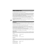
APPENDIX A: TROUBLESHOOTING Normal LED Meanings This section describes the normal operation of the SuperStack II bridge/router LEDs. System LEDs The following figure describes the system LEDs. yy y ,, , ,, y yy , Normal operation Run Aux Power /Fault Fwd Power /Fault Fwd Load Status Lights green when unit has power. Lights amber if there is a problem with power. When unlit, power to unit is off. Test ,y y, SYSTEM Flashes green each time a packet is forwarded between two ports.
Normal LED Meanings WAN LEDs 125 The following figure describes the WAN LEDs when an ISDN or a CSU/DSU connection is being used. The CSU/DSU uses only the B1 LEDs. (CSU/DSU) B1 B2 WAN (CSU/DSU) B1 B2 Line Act Link Lights green when the path is up. Connect Lights green when an end-to-end connection exists or is in progress. Fault Lights amber when an error in the frames is detected. Link Connect Line Error Fault ISDN only Normal operation LAN LEDs L2 (D channel).
APPENDIX A: TROUBLESHOOTING Error LED Meanings Troubleshooting During the Load Phase This section describes the error modes of the SuperStack II bridge/router LEDs. If the Load and Power/Fault LEDs in the System area light amber, a problem occurred during the system software load phase. Compare your System LEDs with the following examples and follow the instructions for troubleshooting. Run Status Amber Aux Load Amber Test Fwd Power /Fault SYSTEM Meaning: Action: The file system is empty.
Error LED Meanings Run Status Amber Aux Load Amber Test Fwd Power /Fault SYSTEM Meaning: Action: 127 The software image file has been deleted or the boot source and image names do not match. Follow these steps: 1 At the monitor prompt, enter: DF The default path is: DF /primary The image is called boot.68k. 2 If the image has been deleted, reload the software using Appendix B.
APPENDIX A: TROUBLESHOOTING load. If the load is unsuccessful, contact your network supplier. Run Status Amber Aux Load Amber Test Fwd Power /Fault SYSTEM Meaning: Action: File read or decompression error. Reload the software. See Appendix B. Run Status Amber Aux Load Amber Test Fwd Power /Fault SYSTEM Meaning: Action: File checksum error. Reload the software. See Appendix B. Run Status Amber Test SYSTEM Meaning: Action: Aux Load Amber Fwd Power /Fault Unspecified fatal error.
Error LED Meanings Run Status Amber Aux Load Amber Test Fwd Power /Fault SYSTEM Meaning: Action: Unable to transmit BOOTP request. Check cable connections. The bridge/router may not be connected correctly to the Ethernet network. Run Status Amber SYSTEM Action: Aux Load Test Meaning: 129 Amber Fwd Power /Fault No response to BOOTP request. The BOOTP server may not be present or is incorrectly configured.
APPENDIX A: TROUBLESHOOTING Run Status Amber Aux Load Amber Test Fwd Power /Fault SYSTEM Meaning: Action: No response from the TFTP server to Address Resolution Protocol (ARP) request. The TFTP server is not present or may be incorrectly configured. Check the TFTP server configuration and verify the MAC address of the bridge/router. Turn the power off and then on again to retry the system software load. If the load is unsuccessful, contact your network supplier for assistance.
Error LED Meanings Troubleshooting During the Test Phase When the software load is complete, the system begins the test phase. If the Test LED lights amber, a problem occurred during the system test phase. Run Status Green Load Amber Test Meaning: Action: Aux Amber Fwd Power /Fault SYSTEM Errors Indicated by the Serial LEDs 131 EEPROM checksum test failed. Contact your network supplier.
APPENDIX A: TROUBLESHOOTING Errors Indicated by the WAN LEDs This section describes how the WAN LEDs indicate errors on systems using ISDN or CSU/DSU connections. WAN (CSU/DSU) B1 B2 Line Act Amber Meaning: Action: Link Connect Line Error Fault Indicates a loss of signal, possibly due to a disconnected cable. Check all cable connections.
Performing Loopback Tests Performing Loopback Tests Response to Local Loopback Assertion 133 This section describes the bridge/router response to a local loopback assertion and how to perform a loopback diagnostic test on the WAN and serial ports. It also describes the steps required to perform additional types of loopback tests for a T1/FT1 module.
APPENDIX A: TROUBLESHOOTING To perform a loopback test on the built-in ISDN port, follow these steps: 1 Assign each path to separate ports, if necessary, by entering: ADD !3 -PORT PAths 3.1 ADD !4 -PORT PAths 3.2 2 Set the rate adaption parameter to automatically detect the speed of the sending interface using: SETDefault ! -PAth RateAdaption = Auto In the example shown in Figure 9, the test originates from path 3.2 and targets 3.1. To specify path 3.2, enter: SETDefault !3.
Performing Loopback Tests 135 8 Start the DLtest using: DLTest Start , To start the DLTest and designate port 4 to send the DLTest data and port 3 to receive and loop back the data, you would enter: DLtest START 4,3 The loopback test is successful when the number of received packets equals or approximately equals the number of transmitted packets. If the test is not successful, verify that your bridge/router is cabled and installed correctly.
APPENDIX A: TROUBLESHOOTING Before running the CSU/DSU loopback test: ■ Attach a console or Telnet to your bridge/router. ■ Cable your WAN port to the telco network. ■ Make sure the device you are connecting to supports V.54 loopback and is in loopback mode. To perform a V.
Performing Loopback Tests 137 6 To determine the current status of the loopback test, either locally-initiated or remotely-initiated, and to determine if the V.54 loopback detection is on, enter: SHow -SYS V54Lback Performing a Local Loopback Test on the CSU/DSU Port (45x and 55x) This section describes how to perform a local loopback test using the loopback plug on the built-in 56/64 Kbps CSU/DSU on the model 45x and 55x bridge/router.
APPENDIX A: TROUBLESHOOTING 5 Specify the number of seconds that the test should run using: DLTest TestDuration If you do not enter a value, the test will run indefinitely. However, use caution when running the test for a specified duration. The test ends abruptly as soon as the time duration expires, and a discrepancy between the number of packets transmitted and the number received may result.
Performing Loopback Tests Performing a Remote Loopback Test on a 56/64 Kbps CSU/DSU Module 139 This section describes how to perform a loopback test on a 56/64 Kbps CSU/DSU module. Figure 12 shows the data flow that occurs when this loopback test is performed.
APPENDIX A: TROUBLESHOOTING 3 Start remote loopback test using: RemtLpbck ! -PAth [Status | RemtCsuLbkStart | RemtDsuLbkStart | RemtCsuLbkEnd | RemtDsuLbkEnd ] To start the remote CSU loopback test on path 2, enter: RemtLpbck !3 -PAth RemtCsuLbkStart To start the remote DSU loopback test on path 2, enter: RemtLpbck !3 -PAth RemtDsuLbkStart 4 To view the status of the loopback test in progress, enter: RemtLpBck !3 -PAth Status The following fields are displayed: Loopback Loopback Loopback Loo
Performing Loopback Tests Performing a Local Loopback Test on the T1/FT1 Port (46x and 56x) 141 This section describes how to perform a local line or payload loopback test using the loopback plug on the T1/FT1port on the model 46x and 56x bridge/router. Figure 13 shows the data flow that occurs when this loopback test is performed. Figure 13 T1/FT1 Local Loopback Testing T1/FT1 port with loopback plug Before running the T1/FT1 loopback test, attach a console or Telnet to your bridge/router.
APPENDIX A: TROUBLESHOOTING 5 Reenable the WAN port by entering: SETDefault !3 -PATH CONTrol = Enable Failure to perform this step causes the port to remain in loopback mode preventing connectivity through the port. Performing diagnostics on the port will reveal only that the port is down. Performing a Remote Loopback for V.54 on a T1/FT1 Port To perform a remote loopback test for V.
Performing Loopback Tests Performing a Remote ANSI Loopback Test on the T1/FT1 Port 143 This section describes how to perform a remote loopback test for ANSI on a T1/FT1 port. Connect your bridge/router to another bridge/router or to a remote device that supports ANSI.
APPENDIX A: TROUBLESHOOTING Performing a Loopback Test on a Serial Port This section describes how to perform a loopback test on a serial port. Figure 14 shows the data flow that occurs when a loopback test is performed on a serial line. A modem or CSU/DSU is required in this configuration. Figure 14 Serial Loopback Testing Before running the serial loopback test, complete the following tasks: ■ Attach a console or Telnet to your bridge/router.
Performing a Memory Dump 145 If the number of received packets equals or approximately equals the number of transmitted packets, your serial line has passed the serial loopback test. If your serial line does not pass the test, verify that your bridge/router is cabled correctly and that the software is configured correctly.
APPENDIX A: TROUBLESHOOTING Notice to users with UNIX TFTP servers: Some UNIX TFTP servers do not have the capability to create files if they do not exist, but can overwrite an existing file. Therefore, you must first create a file with the expected dump file name on the UNIX TFTP server. The procedure for creating such a file is described in “Creating a File for the Memory Dump” on page 147.
Performing a Memory Dump 147 c If necessary, select Gateway from the Dump Destination menu and enter the IP address of the default gateway leading to the network on which the TFTP server resides. d If subnet masks are in use, select Subnet Mask from the Dump Destination menu and enter the subnet mask associated with the IP network attached to the Ethernet port. 8 Select Dump Destination Directory on the Dump Destination menu to configure the location on the TFTP server to which the dump file will go.
APPENDIX A: TROUBLESHOOTING To create a memory dump file, follow these steps: 1 On a UNIX TFTP server, create a file with the name dmXXXXXX.dmp, where XXXXXX is the last six characters of the MAC address of the Ethernet port (port 1) of the SuperStack II bridge/router. For example, if the last six characters of the MAC address of the bridge/router are 06BA6A, enter: touch dm06BA6A.dmp 2 Ensure that all users have permission to write to the target directory and filename.
Performing a Memory Dump Verifying the Memory Dump Procedure 149 To verify that the memory dump process works, simulate a failure of the SuperStack II bridge/router. At the Enterprise OS # prompt, enter: su dm ffffff The system responds with the following information: Bus Error Address = 0xFFFFFF Status word = 0x0015 Instruction = 0x1012 PC = 0x4A2244 Dumping memory to network ... Dumping to file Trying AUI port ... No Carrier on AUI port trying 10BaseT port ...
APPENDIX A: TROUBLESHOOTING
B RELOADING THE SYSTEM SOFTWARE This chapter describes how to reload your system software if the following conditions occur: ■ The boot image has been accidentally deleted or corrupted. ■ The device is unable to boot. To reload the software, you must have the software installed on a trivial file transfer protocol (TFTP) server on the LAN. You can also use a TFTP/ Bootstrap Protocol (BOOTP) server. Install the software on your server from the CD-ROM.
APPENDIX B: RELOADING THE SYSTEM SOFTWARE 2 If you are using a TFTP server (without BOOTP), enter: CL The CL command allows you to configure the following settings: 1. 2. 3. 4. 5. 6. 7. 8. Client Server Gateway Subnet Mask Boot Filename Port Selection Baud Rate Duplex Mode When addressing is configured using the CL command, you do not need to use a BOOTP server to acquire addresses.
SYNTAX CONVENTIONS C This appendix describes Enterprise OS software syntax conventions. Full Form Syntax You can see the full form syntax provided by the online help in the software by typing a question mark (?) or a question mark with other options as described in “Getting Help” on page 160. Figure 15 is an example of full form syntax and includes callouts to the parts and symbols that make up the command syntax. For more information on symbols, see “Symbols” on page 154.
APPENDIX C: SYNTAX CONVENTIONS Abbreviated Syntax The abbreviated syntax shown in uppercase is the shortest unambiguous abbreviation of a command, parameter, or value that can be entered. You can enter the abbreviated form in lower- or uppercase letters at the Enterprise OS prompt. Figure 16 shows the abbreviated version of the syntax shown in Figure 15. Figure 16 Abbreviated Syntax Commands, parameters, and service names can be entered in abbreviated form.
Full and Abbreviated Syntax Examples 155 Table 18 Command Syntax Symbols (continued) Symbol Description vertical bar | Separates mutually exclusive items in a list, one of which must be entered. For example, in the syntax: SET ScreenLength = [None | (6–100)] you can specify either the keyword None or enter a number between 6 and 100 when entering the command. ellipsis ...
APPENDIX C: SYNTAX CONVENTIONS The following abbreviated command specifies that a neighbor on port 2 network number &10 with address %080002030ef2 receives Routing Internet Protocol (RIP) and Service Access Point (SAP) updates: ADD !2 -NRIP ATN &10%080002030ef2 The full form syntax: SETDefault -IP CONTrol = ([ROute | NoROute], [RelaySrcRoute | NoRelaySrcRoute], [SplitLoad | NoSplitLoad], [Filtering | NoFiltering], [SECurity | NoSECurity], [FwdSubnetBcast | NoFwdSubnetBcast], [FwdAllSubnetBcast] | NoF
Using Aliases Entering Service Names in Command Lines 157 When you are configuring or displaying a parameter, service names must be provided to differentiate commands that appear in more than one service. The service name may be entered in abbreviated form. The service name must be preceded by a hyphen. For example, to indicate BRidge Service, type -br. Abbreviated service names are indicated in uppercase in this guide.
APPENDIX C: SYNTAX CONVENTIONS Command History Substitution The bridge/router “remembers” the 10 most recent commands you entered. To display a list of these commands, enter: SHow History To repeat any of the commands displayed, use the event designator, which is represented by an exclamation point (!). Table 19 describes history substitution option syntax. Table 19 History Substitution Option Syntax Syntax Description !! Repeats the previous command. ! Repeats the command line numbered n.
Privilege Level Privilege Level 159 The privilege level determines which commands and parameters you can access. If you log on to the bridge/router with root login, your privilege level is Network Manager, which allows you access to all the commands and parameters. You can create users with either User or Network Manager privilege. Some commands are available only to root. For more information, see “Adding User Accounts” on page 60.
APPENDIX C: SYNTAX CONVENTIONS channel number (.), for example, 3.1. When specifying both a connector and channel number, you must separate the two numbers with a decimal point. If you do not specify a channel number in a command syntax that requires a connector and channel number, the bridge/router assumes the first channel associated with the specified connector.
Getting Help 161 Table 20 Online Help Syntax Summary (continued) Syntax Description - ? Displays a list of commands within the selected service. For example, to display a list of commands in the SYS Service, enter the following command: -SYS? If there are no commands under the service you specify, a message is displayed to indicate this. For example: -IDP? No commands available in IDP service - ? Displays a list of parameters within the selected service.
APPENDIX C: SYNTAX CONVENTIONS
CONNECTORS AND CABLES D This chapter describes each connector and the cables that can be used with each connector on the bridge/router. Console Connector and Cables You can connect a PC running a terminal emulation program, a terminal, or a modem to the Console connector on the SuperStack II bridge/router. WARNING: To eliminate cable noise emission in excess of FCC Part 15, Subpart J, and EN55022 B, this device cable should be shielded and have connectors with metallic backshells.
APPENDIX D: CONNECTORS AND CABLES Terminal Cable Figure 18 shows the pinouts for a 9-pin female to 25-pin null modem-type cable.
LAN Connector and Cables LAN Connector and Cables 165 The two Ethernet connectors, labeled L1 and L2, can be cabled using either 10BASE-T or 100BASE-TX cabling. Boundary router models can use only the L1 Ethernet port. If you upgrade to full router software, the second port will be functional. The following figure shows the pinouts of the L1 and L2 connectors (RJ-45). The connector bodies connect the cable shield to chassis ground.
APPENDIX D: CONNECTORS AND CABLES Cabling Standards Cabling should be installed in accordance with the following standards: 100BASE-TX Cabling ■ EIA/TIA-568 – Commercial building telecommunications wiring standard ■ TSB-36 – Additional cable specifications for unshielded twisted pair cables ■ IBM cabling guidelines Table 22 lists supported 100BASE-TX cable types and emissions classes.
LAN Connector and Cables 167 To create a valid collision domain diameter, you must adhere to the following maximum cable span lengths along with the collision domain diameter guidelines in Table 22: ■ UTP (running TX or T4) — Maximum cable span length is ≤100 m. ■ Fiber (running FX) — Maximum cable span length is ≤412 m. Figure 21 shows examples of collision domain diameters.
APPENDIX D: CONNECTORS AND CABLES For expanded guidelines, refer to the IEEE Standard 802.3.
LAN Connector and Cables Figure 24 Collision Domain Diameter with Two Repeaters Fast Eth ernet R epeate r DTE device Fast Eth ernet R epeate DTE device SuperS tac NETBu k II ilder r 169
APPENDIX D: CONNECTORS AND CABLES Table 23 Maximum Cable Length in Example Collision Domain Diameters Maximum Combined Cable Length, by Interface Scenario TX and/or T4 FX Only FX & TX FX & T4 No Repeaters (see Figure 22) 100 m 412 m not applicable not applicable One Class 1 repeater* (see Figure 23) 200 m — 100 m max. on each side of the repeater 272 m 260.8 m 231 m 100 m max. TX 100 m max. T4 Remaining length of FX Remaining length of FX 308.8 m 304 m‡ 100 m max. TX 100 m max.
WAN Connector and Cables 171 Figure 25 shows the pin assignments of the ISDN S/T cable. Figure 25 ISDN S/T Cable To WAN port To wall outlet or NT1 1 2 34 5 67 8 1 2 34 5 67 8 RJ-45 male (shielded) RJ-45 male (shielded) Name Not connected Not connected Transmit Data+ Receive Data+ Receive DataTransmit DataNot connected Not connected Abbr. Pin NC 1 NC 2 TxD+ 3 RxD+ 4 RxD- 5 TxD- 6 NC 7 NC 8 Pin 1 2 3 4 5 6 7 8 Abbr.
APPENDIX D: CONNECTORS AND CABLES ISDN U Cable To connect a model 44x or model 54x bridge/router to an ISDN network, use a Category 5 shielded twisted-pair cable with an RJ-45 connector on the bridge/router end, and an RJ-11 connector at the wall. This cable comes with your bridge/router. Figure 26 shows the pinouts of the ISDN U cable.
WAN Connector and Cables 56/64K CSU/DSU Cable 173 To connect a model 45x or model 55x bridge/router to a data digital service (DDS), use a cable with an RJ-48S connector. 3Com supplies this cable. Figure 27 shows the pin assignments of the cable with both ends terminated in RJ-48S connectors. Figure 27 CSU/DSU Cable To WAN port To wall outlet 1 2 34 5 67 8 1 2 34 5 67 8 RJ-48S male (shielded) RJ-48S male (shielded) Name Abbr.
APPENDIX D: CONNECTORS AND CABLES RJ-48 T1 Cable To connect a model 46x or model 56x bridge/router to a T1 or fractional T1 line, use a cable with an RJ-48 connector. 3Com does not supply this cable. Figure 27 shows the pin assignments of the cable with both ends terminated in RJ-48 connectors. Figure 28 RJ-48 T1 Cable To WAN port To wall outlet 1 2 34 5 67 8 1 2 34 5 67 8 RJ-48S male (shielded) RJ-48S male (shielded) Name Abbr.
Serial Connectors and Flex-WAN Cables 175 DTEs include mainframes and automatic teller machines. DCEs include modems and CSU/DSUs. A DCE must always connect to a DTE, and vice versa. If you need to connect a DTE to a DTE, or a DCE to a DCE, you can use a crossover cable between the two devices. For example, a SuperStack II bridge/router is a DTE. To connect the bridge/router to another DTE, such as a mainframe, use a crossover Flex-WAN DCE cable.
APPENDIX D: CONNECTORS AND CABLES Flex-WAN cables can be purchased from 3Com. Table 24 lists each Flex-WAN cable and part number. Cable pinouts are provided in the following sections. Table 24 Flex-WAN Cables Cable Length Cable Type Part Number Pinouts 4 ft. RS-232 DTE (straight-through cable to connect to a DCE) 3C89002 page 177 RS-232 DCE (crossover cable to connect to a DTE) 3C89004 page 178 V.35 DTE (straight-through cable to connect to a DCE) 3C89006 page 179 V.
Serial Connectors and Flex-WAN Cables RS-232 DTE Cable Pinouts 177 This cable connects the bridge/router to an RS-232 DCE.
APPENDIX D: CONNECTORS AND CABLES RS-232 DCE Cable Pinouts This cable connects the bridge/router to an RS-232 DTE.
Serial Connectors and Flex-WAN Cables V.35 DTE Cable Pinouts 179 This cable connects the bridge/router to a V.35 DCE. Figure 33 Flex-WAN and V.
APPENDIX D: CONNECTORS AND CABLES V.35 DCE Cable Pinouts This cable connects the bridge/router to a V.35 DTE. Figure 34 Flex-WAN and V.35 DCE Connectors To SuperStack II NETBuilder 1 2 3 4 5 6 7 8 To DTE 9 10 11 12 13 14 15 C A E K P U Y 34 35 36 37 S 31 32 33 H W AA 30 29 28 27 26 25 24 23 22 21 20 19 18 17 16 38 39 40 41 42 43 44 45 D T X 60 59 58 57 56 55 54 53 52 51 50 49 48 47 46 B F R V 60-pin Flex-WAN connector V.35 female connector . Table 28 V.
Serial Connectors and Flex-WAN Cables X.21 DTE Cable Pinouts 181 This cable connects the bridge/router to an X.21 DCE. Figure 35 Flex-WAN and X.21 DTE Connectors To SuperStack II NETBuilder 1 2 3 4 5 6 7 8 9 10 11 12 13 14 15 To DCE 30 29 28 27 26 25 24 23 22 21 20 19 18 17 16 31 32 33 34 35 36 37 1 38 39 40 41 42 43 44 45 2 3 4 5 6 7 8 60 59 58 57 56 55 54 53 52 51 50 49 48 47 46 9 10 11 12 13 14 15 15-pin male connector 60-pin Flex-WAN male connector . Table 29 X.
APPENDIX D: CONNECTORS AND CABLES X.21 DCE Cable Pinouts This cable connects the bridge/router to an X.21 DTE. Figure 36 Flex-WAN and X.21 DCE Connectors To SuperStack II NETBuilder 1 2 3 4 5 6 7 8 9 10 11 12 13 14 15 To DTE 30 29 28 27 26 25 24 23 22 21 20 19 18 17 16 31 32 33 34 35 36 37 1 38 39 40 41 42 43 44 45 2 3 4 5 6 7 8 60 59 58 57 56 55 54 53 52 51 50 49 48 47 46 9 10 11 12 13 14 15 15-pin female connector 60-pin Flex-WAN male connector . Table 30 X.
Serial Connectors and Flex-WAN Cables RS-449 DTE Cable Pinouts 183 This cable connects the bridge/router to an RS-449 DCE.
APPENDIX D: CONNECTORS AND CABLES Table 31 RS-449 DTE Cable Pinouts (continued) Flex-WAN Connector RS-449 DTE Connector Signal Pin Direction Pin Signal LL/DCD 44 → 10 LLSC Circuit Ground 45 − 37 Circuit Ground Shield Ground 46 Cable Shield 1 Shorting Group 1 48 49 - - Twisted Pair 12 Shield Ground - - - Shorting Group 2 51 52 RS-449 DCE Cable Pinouts - This cable connects the bridge/router to an RS-449 DTE.
Serial Connectors and Flex-WAN Cables 185 Table 32 RS-449 DCE Cable Pinouts (continued) Flex-WAN Connector RS-530 DTE Cable Pinouts RS-449 DCE Connector Signal TxCE/TxC+ TxCE/TxCCircuit Ground Circuit Ground TxC/RxCTxC/RxC+ RxC/TxCERxC/TxCE+ RxD/TxDRxD/TxD+ Nil/LL Circuit Ground Shield Ground Pin 13 14 15 16 23 24 25 26 27 28 29 30 46 Direction → → ← ← ← ← ← ← ← Cable Shield Shorting Group 1 48 49 - Pin 5 23 19 20 26 8 35 17 22 4 10 37 1 Signal ST+ STSGRC SGRC RTRT+ TTTT+ SDSD+ LLSC Ground Shiel
APPENDIX D: CONNECTORS AND CABLES Table 33 RS-530 DTE Cable Pinouts Flex-WAN Connector RS-530 DTE Connector Signal Pin CTS/RTS+ 1 CTS/RTS- Direction Pin Signal ← 5 CTS+ 2 ← 13 CTS- DSR/DTR+ 3 ← 6 DSR+ DSR/DTR- 4 ← 22 DSR- DCD/DCD+ 5 ← 8 DCD+ DCD/DCD- 5 ← 10 DCD- DTR/DSR+ 7 → 20 DTR+ DTR/DSR- 8 → 23 DTR- RTS/CTS+ 9 → 4 RTS+ RTS/CTS- 10 → 19 RTS- TxD/RxD+ 11 → 2 TxD+ TxD/RxD- 12 → 14 TxD- TxCE/TxC+ 13 → 24 TxCE+ TxCE/TxC- 14 → 11
E PROVISIONING YOUR ISDN LINE This appendix provides U.S., Canadian, German, and Dutch provisioning information for the built-in ISDN port on model 43x, 53x, 44x and 54x SuperStack II NETBuilder SI bridge/routers. Ordering U.S. and Canadian ISDN BRI Services To order ISDN service from your telephone company, follow these steps: 1 Call the telephone company and ask for the ISDN representative.
APPENDIX E: PROVISIONING YOUR ISDN LINE ■ Phone Numbers. Ask the telephone representative for your ISDN phone numbers and write them in the space provided. ■ Service Profile ID (SPID) Number. Ask the telephone representative for your SPID numbers. ((For a point-to-point line only one SPID may be provided. For a multipoint line, the telephone representative should provide two SPID numbers.) A SPID number has 10–15 characters; for example, 0155512120. Your switch type may not require the SPID number.
Switch Provisioning Tables This section provides provisioning information for the following switch types in the U.S. and Canada: ■ AT&T 5ESS ■ AT&T 5ESS Custom ■ DMS 100 and National ISDN 1 ■ Siemens EWSD AT&T 5ESS Switch To order ISDN service for an AT&T 5ESS switch, provide the telephone company with the information in Table 34.
APPENDIX E: PROVISIONING YOUR ISDN LINE Table 34 Ordering ISDN Service for an AT&T 5ESS Switch (continued) Required Information Specification CSD CHL Any TERMTYP TYPEA or TYPEE Display No CSD Limit 2 CA PREF 1 AT&T 5ESS Custom Switch To order ISDN service for an AT&T 5ESS custom switch, provide the telephone company with the information in Table 35.
A point-to-point configuration on a SuperStack II bridge/router or boundary router is selected by setting the SPIDn1 and SPIDn2 parameters to none. DMS 100 and National ISDN 1 To order ISDN service for a DMS 100 or National ISDN 1 switch, provide the telephone company with the information in Table 36.
APPENDIX E: PROVISIONING YOUR ISDN LINE Siemens EWSD Switch To order ISDN service for a Siemens EWSD switch, provide the phone company with the information in Table 36.
NT1s and Power Supplies 193 ■ The SPID numbers must be unique. The 2-digit TID can be any number from 0 to 62. The TID has no effect on the operation of the SuperStack II bridge/router, but it is a necessary part of the SPID that the bridge/router uses to gain access to the ISDN network. ■ If you request ISDN service from a Northern Telecom DMS-100 service provider, the format is: Area code + 7-digit telephone number + 0 to 8 digit suffix + 2 digit TID.
APPENDIX E: PROVISIONING YOUR ISDN LINE Ordering German ISDN BRI Services To order German ISDN services, follow these steps: 1 Acquire a form entitled “Telefondienstauftrag im ISDN (Euro-ISDN-Anschluß)” from the Telekom. 2 At the top of the form, select “Neuanschluß.” 3 Under “Auftraggeber,” provide the requested information. 4 Under “Anschluß,” specify “Basisanschluß als Standardanschluß.
Ordering Dutch ISDN BRI Services Ordering Dutch ISDN BRI Services 195 To order ISDN services from the Dutch PTT, follow these steps: 1 Acquire a form entitled "Aanvraag formulier ISDN aansluiting from the Dutch PTT." 2 Under 1, specify “Nieuwe ISDN-aansluiting". 3 Under 3, specify the requested connection date. 4 Under 4, specify "Enkelvoudige ISDN-2 aansluiting". 5 Under 7, specify how many phone numbers you want to assign to the ISDN line (MSN). 6 Under 8, specify any extra services required.
APPENDIX E: PROVISIONING YOUR ISDN LINE
F TECHNICAL SUPPORT 3Com provides easy access to technical support information through a variety of services. This appendix describes these services. Information contained in this appendix is correct at time of publication. For the very latest, 3Com recommends that you access the 3Com Corporation World Wide Web site.
APPENDIX F: TECHNICAL SUPPORT To connect to the 3Com FTP site, enter the following information into your FTP client: ■ Hostname: ftp.3com.com (or 192.156.136.12) ■ Username: anonymous ■ Password: A user name and password are not needed with Web browser software such as Netscape Navigator and Internet Explorer. 3Com Bulletin Board Service The 3Com BBS contains patches, software, and drivers for 3Com products.
Support from Your Network Supplier 3ComFacts Automated Fax Service 199 The 3ComFacts automated fax service provides technical articles, diagrams, and troubleshooting instructions on 3Com products 24 hours a day, 7 days a week. Call 3ComFacts using your Touch-Tone telephone: 1 408 727 7021 Support from Your Network Supplier If additional assistance is required, contact your network supplier.
APPENDIX F: TECHNICAL SUPPORT Below is a list of worldwide technical telephone support numbers: Country Telephone Number Country Telephone Number Asia Pacific Rim Australia Hong Kong India Indonesia Japan Malaysia New Zealand Pakistan Philippines 1 800 678 515 800 933 486 61 2 9937 5085 001 800 61 009 0031 61 6439 1800 801 777 0800 446 398 61 2 9937 5085 1235 61 266 2602 P.R. of China 10800 61 00137 or 021 6350 1590 800 6161 463 Singapore S. Korea From anywhere in S.
Returning Products for Repair Returning Products for Repair 201 Before you send a product directly to 3Com for repair, you must first obtain a Return Materials Authorization (RMA) number. Products sent to 3Com without RMA numbers will be returned to the sender unopened, at the sender’s expense.
INDEX SYMBOLS 100BASE-TX cable 166 connector 165 100mb LED 125 10BASE-T cable 165 connector 165 3Com bulletin board service (3Com BBS) 198 3Com URL 197 3ComFacts 199 Baud parameter 76 baud rate, console port configuring 60 default 60 Boot command 121 boot path 121 BOOTP server 108, 151 boundary router active ports 34 cabling Ethernet 34 Boundary Routing, central node 101 BRI 24 bridging 101 per-port 102 BT command 121 bulletin board service 198 A C ? command 123 Numerics abbreviated syntax 154 Activ
INDEX CE notice 5 central node, configuring for Boundary Routing 101 channels B 24 D 24 command-line interface accessing 56, 57 components of 57 service names 157 short cuts abbreviated syntax 153 aliases 157 history substitution 158 syntax abbreviated description 154 examples 155 full form description 153 symbols used 154 commands ? 123 AddUser 60 Boot 121 BT 121 DELeteUser 60 DF 122 Display Files 122 entering 57 H 123 Help 123 help on 160 history substitution 158 MEnu 56, 57 overview 56 PassWord 60
INDEX dial number lists 113 dial-on-demand 90 dial pool configuring ISDN 82 configuring serial 87 dynamic paths 64 dial-up configuring 79 dial number list editing 114 using 113 to 114 IPX routing 109 using OSPF 107 DialCONTrol parameter 64 dial-up lines description 25 disaster recovery 92 Display Files command 122 DMS 100 switch, ordering 191 documentation CD-ROM 29 Dump Destination firmware parameter 146 duplex Ethernet 70 dynamic paths 64 dynamic routing protocols 106 E electromagnetic compatibility inf
INDEX adding 109 Override option 110 IPXWAN 109 ISDN acquiring telecommunication services 194, 195 BRI 24 cable 170, 172 cabling the connector S/T 35 U 35 description 24 German BRI services 194 information sheet 188 loopback testing 133 North American BRI services 187 port 24 provisioning tables 189 SPIDs 192 switch types 71 default 71 ETSI 54 supported 72 TA, configuring 75, 86 L LAN cabling the connector 34 LAN LEDs 125 leased lines, description 25 LEDs error meanings 126 LAN 125 Line Act with ETSI
INDEX P packet-switched services 25 parameters Baud 76 COMmunity 62 DialCONTrol 64 ISDN switch types 72 LocalDialNo 70 LocalSubAddr 71 overview 56 PAths 65, 92 RemoteManager 62 selecting 57 SPIDdn1, SPIDdn2 72 SpidWIZard 70 SysCONtact 61 SysLOCation 61 SysNAMe 61 parent ports 68 partially meshed topology, Frame Relay 95 PassWord command 60 passwords changing 59 default 59 PATH service Baud parameter 76 DialCONTrol parameter 64 ExDevType parameter 76 LocalDialNo parameter 70 LocalSubAddr parameter 71 SPIDdn
INDEX recommended serial devices 21 services packet-switched 25 telco 25 shipping carton contents 29 shutting down 39 Siemens EWSD switch, ordering 192 simple network management protocol.
INDEX command-line 56 ISDN variation 159 menu-driven 56 User privilege 59 UserManage command 61 V V.35 DCE connector described 25 V.35 DTE connector 25 virtual ports configuring dial pool 85, 89 configuring Frame Relay 94, 95 configuring X.25 98 definition 65 inherited attributes 68 naming restrictions 111 over Frame Relay and X.25 66 PPP 67 W WAN LEDs 125 WAN port configuring CSU/DSU 74 configuring ISDN 70 World Wide Web (WWW) 197 X X.
INDEX
3Com Corporation LIMITED WARRANTY HARDWARE 3Com warrants its hardware products to be free from defects in workmanship and materials, under normal use and service, for the following lengths of time from the date of purchase from 3Com or its authorized reseller: Network Interface Cards Lifetime Other hardware products *unless otherwise specified above 1 year* Spare parts and spares kits 90 days If a product does not operate as warranted above during the applicable warranty period, 3Com shall, at its op