SS2TRHWBook Page i Monday, May 5, 1997 3:11 PM ® Installing the SuperStack® II NETBuilder® Token Ring and FRAD Bridge/Router Models 32x and 52x http://www.3com.com/ Part No.
SS2TRHWBook Page ii Monday, May 5, 1997 3:11 PM 3Com Corporation 5400 Bayfront Plaza Santa Clara, California 95052-8145 Copyright © 3Com Corporation, 1997. All rights reserved. No part of this documentation may be reproduced in any form or by any means or used to make any derivative work (such as translation, transformation, or adaptation) without permission from 3Com Corporation.
SS2TRHWBook Page iii Monday, May 5, 1997 3:11 PM Modifications Modifications or changes made to this device, and not approved by 3Com, may void the authority granted by the FCC, or other such agency, to operate this equipment. Shielded Cables Connections between 3Com equipment and other equipment and peripherals must be made using shielded cables in order to maintain compliance with FCC, and other agency, electromagnetic frequency emissions limits.
SS2TRHWBook Page iv Monday, May 5, 1997 3:11 PM CE Notice Marking by the following symbol indicates compliance of this equipment with the EMC and Telecom Directives of the European Community. Such marking is indicative that this equipment meets or exceeds the following technical standards: iv ■ EN 55022 — Limits and methods of measurement of radio interference characteristics of information technology equipment.
SS2TRHWBook Page v Monday, May 5, 1997 3:11 PM CONTENTS ABOUT THIS GUIDE Conventions 1 1 INSTALLING THE HARDWARE Required Equipment 1-1 Mounting 1-3 Rack-Mount Kit 1-3 Installing on a Tabletop 1-3 Stacking with Brackets 1-4 Installing in a Rack 1-4 Cabling the Connectors 1-5 Cabling the LAN Connector (Models 323, 327, and 52x) Cabling the ISDN Connector (Model 52x) 1-6 Cabling the Serial Connectors 1-7 Models 32x (DTE mode) 1-8 Models 32x (DCE-like mode) 1-8 Models 52x (DTE mode) 1-9 Models 52x (DCE-li
SS2TRHWBook Page vi Monday, May 5, 1997 3:11 PM Connectors and Cables 2-3 Console Cables 2-3 PC Cable 2-4 Terminal Cable 2-5 Modem Cable 2-6 LAN Connectors and Cables 2-6 UTP Connector and Cable 2-6 STP Connector and Cable 2-7 Cabling Standards 2-8 Serial Cables 2-9 V.35 to V.35 DCE Cable (32x) 2-9 V.35 to V.35 Direct Connect Cable (32x) 2-10 UNIVERSAL to V.35 Adapter Cable 2-11 UNIVERSAL to V.35 Direct Connect Cable 2-12 UNIVERSAL to RS-449/V.36 DCE Cable 2-13 UNIVERSAL to RS-449/V.
SS2TRHWBook Page vii Monday, May 5, 1997 3:11 PM A PROVISIONING YOUR ISDN LINE Ordering North American ISDN BRI Services North American Switch Provisioning Tables AT&T 5ESS Switch A-4 AT&T 5ESS Custom Switch A-5 DMS 100 and National ISDN A-6 Siemens EWSD Switch A-7 SPIDs A-7 NT1s and Power Supplies A-8 Ordering German ISDN BRI Services A-9 B A-1 A-3 TECHNICAL SUPPORT Online Technical Services B-1 World Wide Web Site B-1 3Com Bulletin Board Service B-1 Access by Analog Modem B-2 Access by Digital Modem
SS2TRHWBook Page viii Monday, May 5, 1997 3:11 PM viii
SS2TRHWBook Page 1 Monday, May 5, 1997 3:11 PM ABOUT THIS GUIDE This guide includes complete hardware installation and cabling information for your SuperStack® II NETBuilder® bridge/router model 32x or 52x.
SS2TRHWBook Page 2 Monday, May 5, 1997 3:11 PM 2 CHAPTER : ABOUT THIS GUIDE
SS2TRHWBook Page 1 Monday, May 5, 1997 3:11 PM INSTALLING THE HARDWARE 1 This chapter describes how to install your SuperStack II NETBuilder bridge/router. Required Equipment Table 1-1 Table 1-1 lists the items you receive in the shipping carton and items you need to provide.
SS2TRHWBook Page 2 Monday, May 5, 1997 3:11 PM 1-2 CHAPTER 1: INSTALLING THE HARDWARE Table 1-1 Equipment Received and Equipment Needed (continued) What you need to provide (continued) For serial connection, provide the following: Channel service unit/digital service unit (CSU/DSU) device or modem if desired Up to three of the following cables: X.21 or V.35 adapter cable UNIVERSAL connector to RS-449/V.36 data communications equipment (DCE) cable UNIVERSAL to RS-232 DCE cable UNIVERSAL to V.
SS2TRHWBook Page 3 Monday, May 5, 1997 3:11 PM Mounting Mounting Rack-Mount Kit You can mount your bridge/router on a tabletop, stack it, or mount it in a rack.
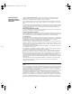
SS2TRHWBook Page 4 Monday, May 5, 1997 3:11 PM 1-4 CHAPTER 1: INSTALLING THE HARDWARE Stacking with Brackets The stacking brackets can be used to securely stack several bridge/routers on a tabletop. Use the stacking brackets and the M4x8 mm panhead stacking screws shown in Figure 1-1.
SS2TRHWBook Page 5 Monday, May 5, 1997 3:11 PM Cabling the Connectors 1-5 2 Hold the chassis between the poles of the rack and attach the brackets to the rack using panhead screws (you must provide these screws). Tighten each screw securely. CAUTION: Using fewer than two screws to secure the brackets to the rack may cause the boundary router to fall and sustain damage not covered by the warranty.
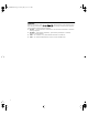
SS2TRHWBook Page 6 Monday, May 5, 1997 3:11 PM 1-6 CHAPTER 1: INSTALLING THE HARDWARE Cabling the LAN Connector (Models 323, 327, and 52x) This section applies to models 323, 327, and 52x only. You can use only one type of LAN connector on each bridge/router. The following figure shows how to cable a LAN connector. LAN UTP STP 16Mb Active Fault UTP cable STP cable OR For more information on AUI and 10BASE-T cables, refer to Chapter 2.
SS2TRHWBook Page 7 Monday, May 5, 1997 3:11 PM Cabling the Connectors Cabling the Serial Connectors 1-7 The serial connectors provide the following options: The UNIVERSAL connector can be converted to a V.35, V.36, X.21, RS-449, or RS-232 connector. ■ All serial connectors can function in either DTE or DCE-like mode, which allows you to connect a serial connector to either a CSU/DSU device or modem (DTE mode), or to an IBM cluster controller (DCE-like mode).
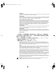
SS2TRHWBook Page 8 Monday, May 5, 1997 3:11 PM 1-8 CHAPTER 1: INSTALLING THE HARDWARE The following figures show how to cable the serial connectors. Models 32x (DTE mode) SuperStack II NETBuilder SERIAL V.35 (A) A B C UNIVERSAL (B) RS-232 (C) Link Run Console Active Load Status Fault Test Fwd Power /Fault SYSTEM RS-232 DCE cable V.35 DCE cable V.35 adapter X.21 adapter RS-449/V.36 DCE or RS-232 DCE cables Models 32x (DCE-like mode) SuperStack II NETBuilder SERIAL B C V.
SS2TRHWBook Page 9 Monday, May 5, 1997 3:11 PM Cabling the Connectors Models 52x (DTE mode) ISDN S/T Line Act SERIAL B1 B2 Link B C RS-232 (C) UNIVERSAL (B) Link Connect Line Error Active Fault Fault RS-232 DCE cable V.35 adapter X.21 adapter RS-449/V.36 DCE or RS-232 DCE cables Models 52x (DCE-like mode) ISDN S/T Line Act SERIAL B1 B2 Link B C UNIVERSAL (B) RS-232 (C) Connect Line Error IBM cluster controller Link Active Fault Fault RS-232 direct connect cable V.
SS2TRHWBook Page 10 Monday, May 5, 1997 3:11 PM 1-10 CHAPTER 1: INSTALLING THE HARDWARE Attaching a Redundant Power System You can attach your SuperStack II bridge/router to a SuperStack II Redundant Power System (RPS). You will need to order the connecting cable (part number 3C8101) from 3Com. The following figure shows where to attach this cable.
SS2TRHWBook Page 11 Monday, May 5, 1997 3:11 PM Connecting a PC, Terminal, or Modem Connecting a PC, Terminal, or Modem 1-11 Connect a PC running a terminal emulation program, a terminal, or a modem to the Console port on the SuperStack II bridge/router to configure the bridge/router software and review startup and system operation messages. To connect a PC, terminal, or modem to the DPE module, follow these steps: 1 Obtain a cable to connect the console to the Console port on the bridge/router.
SS2TRHWBook Page 12 Monday, May 5, 1997 3:11 PM 1-12 CHAPTER 1: INSTALLING THE HARDWARE Shutting Down If your SuperStack II system is not connected to an RPS, turn off the power by pressing the off (0) side of the power switch on the back panel. If your system is connected to an RPS, turn off the power by unplugging the RPS cable from the system and then pressing the off (0) side of the power switch.
SS2TRHWBook Page 1 Monday, May 5, 1997 3:11 PM OVERVIEW 2 This chapter provides an overview of the SuperStack II NETBuilder bridge/router, including information on: Model Features Table 2-1 ■ Model features ■ Chassis panels ■ LEDs ■ DIP switches ■ Hardware interrupt switch ■ Connectors and cables ■ Physical specifications Table 2-1 lists each SuperStack II NETBuilder model along with memory, port, and upgrade information.
A B C UNIVERSAL (B) 16Mb SuperStack II NETBuilder SERIAL V.35 (A) STP RS-232 (C) Link Active Active Fault Fault Run Console Status Load Test Fwd Power /Fault SYSTEM Figure 2-1 Chassis Front Panels Line Act LED ISDN LAN UTP S/T STP 16Mb Active Fault Line Act RS-232 connector UNIVERSAL connector STP 16Mb V.
SS2TRHWBook Page 3 Monday, May 5, 1997 3:11 PM LEDs MODEL: ESPL-310 NETBUILDER REMOTE OFFICE 222 100-240VAC, 50/60HZ, 1.0-0.5A 250V, F2A S/N: 1SC05427 NTWK ADDR: FOR CONTINUED PROTECTION AGAINST FIRE HAZARD REPLACE FUSE ONY WITH SAME TYPE AND RATING 3COM CORP. 2-3 8.3 080002 04BA1E 04BA1F 04BA20 04BA21 LAN WAN-A WAN-B WAN-C 07/31/95 SANTA CLARA, CA.
SS2TRHWBook Page 4 Monday, May 5, 1997 3:11 PM 2-4 CHAPTER 2: OVERVIEW PC Cable Figure 2-3 shows the pinouts for a 9-pin female to 9-pin female PC cable. A null modem-type cable may be used.
SS2TRHWBook Page 5 Monday, May 5, 1997 3:11 PM Connectors and Cables 2-5 Terminal Cable Figure 2-4 shows the pinouts for a 9-pin female to 25-pin terminal cable. A null modem-type cable may be used.
SS2TRHWBook Page 6 Monday, May 5, 1997 3:11 PM 2-6 CHAPTER 2: OVERVIEW Modem Cable Figure 2-5 shows the pinouts for a 9-pin female to 25-pin male modem cable. A straight-through-type cable may be used.
SS2TRHWBook Page 7 Monday, May 5, 1997 3:11 PM Connectors and Cables Table 2-2 2-7 UTP Cable Types, MAUs, and Emissions Compliance Emissions Compliance* MAUs Passive Active Retimed Category 3 no yes yes no Category 4 yes yes yes no Category 5 yes yes yes no Shielded 100 ohm: UTP† Category 3 no yes yes yes Category 4 yes yes yes yes Category 5 yes yes yes yes Cable Type UTP† FCC and VCCI Class A EN55022 and VDE Class B 100 ohm: * Shielding of all cable types should be
SS2TRHWBook Page 8 Monday, May 5, 1997 3:11 PM 2-8 CHAPTER 2: OVERVIEW Auxiliary Power. Auxiliary +5 volt power is available on the STP connector for specialty powered MAUs, powered port expanders, or signal conversion devices such as token ring STP-to-fiber optic transceivers. To use the auxiliary power pins, follow the guidelines in Table 2-4. Table 2-4 Auxiliary Pin Use Pinout (STP) Pin 3 Pins 2, 4, 7, 8 Maximum Current +5 volts (+/- 10%), 500 mA (fused at 2.
SS2TRHWBook Page 9 Monday, May 5, 1997 3:11 PM Connectors and Cables Serial Cables 2-9 The following cables can be used with the serial port connectors. V.35 to V.35 DCE Cable (32x) This straight-through cable connects the V.35 port on a bridge/router to a standard V.35 DCE device. To V.
SS2TRHWBook Page 10 Monday, May 5, 1997 3:11 PM 2-10 CHAPTER 2: OVERVIEW V.35 to V.35 Direct Connect Cable (32x) This cable connects a V.35 port of the bridge/router to a V.35 port of an SNA legacy device. To V.35 port on bridge/router To V.35 SNA Device B F L R V Z DD JJ NN B F L R V Z DD JJ NN D J N T X BB FF LL D J N T X BB FF LL A E K P U Y CC HH MM A E K P U Y CC HH MM C H M S W A EE KK C H M S W A EE KK V.35 male connector V.
SS2TRHWBook Page 11 Monday, May 5, 1997 3:11 PM Connectors and Cables 2-11 UNIVERSAL to V.35 Adapter Cable To connect a SuperStack II bridge/router to a V.35 DCE device, cable the UNIVERSAL connector using a V.35 adapter cable. Figure 2-8 shows the pin assignments of the V.35 adapter cable. When constructing your own V.35 adapter cables, the required cable type is equivalent to Belden part number 9835. Cable length is limited to CCITT standard V.11 Appendix I.2.
SS2TRHWBook Page 12 Monday, May 5, 1997 3:11 PM 2-12 CHAPTER 2: OVERVIEW UNIVERSAL to V.35 Direct Connect Cable This cable connects a UNIVERSAL port on the bridge/router to the V.35 port on an SNA legacy device. To SNA device B F L R D J N T A E K P U C H M S W A Pin X Abbr V V.
SS2TRHWBook Page 13 Monday, May 5, 1997 3:11 PM Connectors and Cables 2-13 UNIVERSAL to RS-449/V.36 DCE Cable To connect a SuperStack II bridge/router to a V.36 DCE device, cable the UNIVERSAL connector using a V.36 adapter cable. Figure 2-10 shows the pin assignments of the V.36 adapter cable. When constructing your own V.36 adapter cables, the required cable type is equivalent to Belden part number 9835. Cable length is limited to CCITT standard V.11 Appendix I.2.
SS2TRHWBook Page 14 Monday, May 5, 1997 3:11 PM 2-14 CHAPTER 2: OVERVIEW UNIVERSAL to RS-449/V.36 Direct Connect Cable This cable connects the UNIVERSAL connector on the bridge/router to the RS-449/V.36 port of an SNA legacy device. To UNIVERSAL port on bridge/router 1 2 3 4 5 6 7 8 9 10 11 12 13 14 15 16 17 18 19 20 21 22 23 24 25 26 27 28 29 30 31 32 33 34 35 36 37 To RS449/V.
SS2TRHWBook Page 15 Monday, May 5, 1997 3:11 PM Connectors and Cables 2-15 UNIVERSAL to RS-232 DCE Cable This cable connects the UNIVERSAL port on a SuperStack II NETBuilder bridge/router to an RS-232 interface on a DCE device.
SS2TRHWBook Page 16 Monday, May 5, 1997 3:11 PM 2-16 CHAPTER 2: OVERVIEW UNIVERSAL to RS-232 Direct Connect Cable This cable connects the UNIVERSAL port on the bridge/router to the RS-232 port on an SNA legacy device.
SS2TRHWBook Page 17 Monday, May 5, 1997 3:11 PM Connectors and Cables 2-17 RS-232 to RS-232 DCE Cable This straight-through cable connects the RS-232 port on a SuperStack II bridge/router to a standard RS-232 DCE device. Figure 2-14 shows the pin assignments of the RS-232 cable.
SS2TRHWBook Page 18 Monday, May 5, 1997 3:11 PM 2-18 CHAPTER 2: OVERVIEW RS-232 to RS-232 Direct Connect Cable This cable connects the RS-232 port on the bridge/router to an RS-232 port on an SNA legacy device. To SNA device To RS-232 port on bridge/router 1 2 3 4 5 6 7 8 9 10 11 12 13 1 2 3 4 5 6 7 8 9 10 11 12 13 14 15 16 17 18 19 20 21 22 23 24 25 14 15 16 17 18 19 20 21 22 23 24 25 25-pin male connector 25-pin male connector Name Pin Pin Abbr Name Chas.
SS2TRHWBook Page 19 Monday, May 5, 1997 3:11 PM Connectors and Cables 2-19 UNIVERSAL to X.21 Adapter Cable If you want to connect any of the SuperStack II bridge/routers documented in this guide to an X.21 DCE device, cable the connector marked UNIVERSAL using an X.21 adapter cable. Figure 2-16 shows the pin assignments of the X.21 adapter cable.
SS2TRHWBook Page 20 Monday, May 5, 1997 3:11 PM 2-20 CHAPTER 2: OVERVIEW When constructing your own X.21 adapter cables, the required cable type is equivalent to Belden part number 9839. Cable length is limited to CCITT standard V.11 Appendix I.2. You can order the X.21 adapter cable from 3Com (part number 3C8021). X.21 European Connector Compliances. For installations where compliance to the European standard NET 1 is required, use an X.21 15-pin male connector (ISO 4903) to construct the RS-449-to-X.
SS2TRHWBook Page 21 Monday, May 5, 1997 3:11 PM Physical Specifications Physical Specifications 2-21 Table 2-7 provides the environmental requirements of model 32x and 52x bridge/routers.
SS2TRHWBook Page 22 Monday, May 5, 1997 3:11 PM 2-22 CHAPTER 2: OVERVIEW
SS2TRHWBook Page 1 Monday, May 5, 1997 3:11 PM 3 UPGRADING MEMORY The following memory upgrades are available from 3Com for your bridge/router: ■ 4 MB (3C8104) flash memory ■ 4 MB DRAM (3C8040) Complete the following sections to install flash memory or DRAM in your SuperStack II bridge/router. CAUTION: If you install the flash memory upgrade and then remove it from your system after startup, you will need to reload the system software using the procedures described in the software guide.
SS2TRHWBook Page 2 Monday, May 5, 1997 3:11 PM 3-2 CHAPTER 3: UPGRADING MEMORY CAUTION: Make sure you do not accidentally alter the dip switch settings when you remove the cover. Dip switches should all be in the down position Installing Memory To install the flash memory and/or DRAM SIMM, follow these steps: 1 With the chips facing toward the back of the bridge/router, place the silver connector edge of the SIMM into the appropriate SIMM socket at almost a 90-degree angle.
SS2TRHWBook Page 3 Monday, May 5, 1997 3:11 PM Reinstalling the Cover 3-3 Reinstalling the Cover 1 Reinstall the cover on the SuperStack II bridge/router and reattach it to the chassis with the two screws. 2 Place the upgrade sticker included in your kit on the chassis, as shown. If you have both the flash memory and the DRAM memory upgrade kits, place one sticker from each kit as shown. MODEL: ESPL-310 NETBUILDER REMOTE OFFICE 222 100-240VAC, 50/60HZ, 1.0-0.
SS2TRHWBook Page 4 Monday, May 5, 1997 3:11 PM 3-4 CHAPTER 3: UPGRADING MEMORY
SS2TRHWBook Page 1 Monday, May 5, 1997 3:11 PM TROUBLESHOOTING 4 This chapter describes troubleshooting using the LEDs on the front panel of the system. If the Power/Fault LED appears yellow at any time during the startup process, the bridge/router has encountered a problem during system test or system software load. If the Power/Fault LED appears yellow, check the other LEDs as shown in the following figure.
SS2TRHWBook Page 2 Monday, May 5, 1997 3:11 PM 4-2 CHAPTER 4: TROUBLESHOOTING Troubleshooting During the Test Phase Table 4-1 When a problem occurs during the test phase, the Status LEDs light in a particular pattern. Table 4-1 shows the Status LED pattern, the problem associated with that pattern, and the action to take. System Self-test Errors Status LEDs 1 2 3 4 Test LED Power/Fault LED Meaning and Action Off Off On On On Yellow EEPROM checksum test failed. Contact your network supplier.
SS2TRHWBook Page 3 Monday, May 5, 1997 3:11 PM LED Meanings Table 4-2 4-3 System Software Load Errors (continued) Status LEDs 1 2 3 4 Load LED Power/Fault LED Meaning and Action On On On On On Yellow Write to Flash File System failed. Call your network supplier for assistance. LED Meanings Table 4-3 Model No. Table 4-3 provides the meanings for the lit LEDs on a SuperStack II bridge/router.
SS2TRHWBook Page 4 Monday, May 5, 1997 3:11 PM 4-4 CHAPTER 4: TROUBLESHOOTING Troubleshooting the Token Ring Connection Table 4-4 Symptom This section is not applicable to model 320. Table 4-4 summarizes problems that can occur with a token ring connection and what action you can take.
SS2TRHWBook Page 5 Monday, May 5, 1997 3:11 PM Troubleshooting the Token Ring Connection Table 4-4 4-5 Troubleshooting the Token Ring Connection (Models 327 and 527 only) (continued) Symptom Cause and Action Path 1 is up, but the system does not appear to be communicating with other network devices. The system may have attempted to enter the token ring at the wrong speed. The following error message appears: If your system is the first device to enter the ring, disregard this message.
SS2TRHWBook Page 6 Monday, May 5, 1997 3:11 PM 4-6 CHAPTER 4: TROUBLESHOOTING Table 4-4 Symptom Troubleshooting the Token Ring Connection (Models 327 and 527 only) (continued) Cause and Action The MAC address of the system does The MAC address on the network is in noncanonical format. not appear on the token ring network. The MAC address encoded on the EEPROM and printed on the label is in canonical format and needs to be converted to noncanonical format.
SS2TRHWBook Page 1 Monday, May 5, 1997 3:11 PM A PROVISIONING YOUR ISDN LINE This appendix provides North American (U.S. and Canada) and German provisioning information for the SuperStack II NETBuilder bridge/routers and boundary routers using an Integrated Services Digital Network (ISDN) line with a basic rate interface (BRI). If your ISDN line is not provisioned correctly, you will not be able to use your SuperStack II bridge/router or boundary router to access a remote network.
SS2TRHWBook Page 2 Monday, May 5, 1997 3:11 PM A-2 APPENDIX A: PROVISIONING YOUR ISDN LINE 6 If desired, ask for an NT1 to connect your SuperStack II bridge/router to the ISDN line. (You can also purchase an NT1 from a reseller.
SS2TRHWBook Page 3 Monday, May 5, 1997 3:11 PM North American Switch Provisioning Tables A-3 Your telephone company gives you the phone number and SPID number after it installs your line. If your telephone company has the IOC for a SuperStack II bridge/router or boundary router, you do not need to complete step 8. 8 Provide provisioning information that corresponds to your ISDN switch using the tables in the following sections.
SS2TRHWBook Page 4 Monday, May 5, 1997 3:11 PM A-4 APPENDIX A: PROVISIONING YOUR ISDN LINE AT&T 5ESS Switch To order ISDN service for an AT&T 5ESS switch, provide the telephone company with the information in Table A-1.
SS2TRHWBook Page 5 Monday, May 5, 1997 3:11 PM North American Switch Provisioning Tables AT&T 5ESS Custom Switch A-5 To order ISDN service for an AT&T 5ESS custom switch, provide the telephone company with the information in Table A-2.
SS2TRHWBook Page 6 Monday, May 5, 1997 3:11 PM A-6 APPENDIX A: PROVISIONING YOUR ISDN LINE DMS 100 and National ISDN To order ISDN service for a DMS 100 or National ISDN switch, provide the telephone company with the information in Table A-3.
SS2TRHWBook Page 7 Monday, May 5, 1997 3:11 PM SPIDs Siemens EWSD Switch To order ISDN service for a Siemens EWSD switch, provide the phone company with the information in Table A-3.
SS2TRHWBook Page 8 Monday, May 5, 1997 3:11 PM A-8 APPENDIX A: PROVISIONING YOUR ISDN LINE ■ The SPID numbers must be unique. The 2-digit TID can be any number from 0 to 62. The TID has no effect on the operation of the SuperStack II bridge/router, but it is a necessary part of the SPID that the bridge/router uses to gain access to the ISDN network.
SS2TRHWBook Page 9 Monday, May 5, 1997 3:11 PM Ordering German ISDN BRI Services A-9 Not all NT1s provide phantom power; for example, the AMI NT1 from AT&T does not. If you connect the SuperStack II bridge/router to an NT1 that does not provide phantom power, you must turn off phantom power detection before you can dial successfully. Turn off phantom power detection by setting -PATH PhantomPower to Disable. For more information on this parameter, refer to the software reference guide.
SS2TRHWBook Page 10 Monday, May 5, 1997 3:11 PM A-10 APPENDIX A: PROVISIONING YOUR ISDN LINE
SS2TRHWBook Page 1 Monday, May 5, 1997 3:11 PM B TECHNICAL SUPPORT 3Com provides easy access to technical support information through a variety of services. This appendix describes these services. Information contained in this appendix is correct at time of publication. For the very latest, we recommend that you access 3Com Corporation’s World Wide Web site as described below.
SS2TRHWBook Page 2 Monday, May 5, 1997 3:11 PM B-2 APPENDIX B: TECHNICAL SUPPORT Access by Analog Modem To reach the service by modem, set your modem to 8 data bits, no parity, and 1 stop bit.
SS2TRHWBook Page 3 Monday, May 5, 1997 3:11 PM Support from Your Network Supplier B-3 Local access numbers are available within the following countries: 3ComForum on CompuServe Online Service Country Telephone Number Country Telephone Number Australia 1800 678 515 Netherlands 06 0228049 Belgium 0800 71279 New Zealand 0800 446 398 Denmark 800 17319 Norway 800 11062 Finland 98 001 4444 Portugal 0505 442 607 France 05 90 81 58 Russia (Moscow only) 956 0815 Germany 0130 81 80 63 S
SS2TRHWBook Page 4 Monday, May 5, 1997 3:11 PM B-4 APPENDIX B: TECHNICAL SUPPORT Support from 3Com If you are unable to receive support from your network supplier, technical support contracts are available from 3Com. Contact your local 3Com sales office to find your authorized service provider using one of these numbers: Regional Sales Office 3Com Corporation P.O. Box 58145 5400 Bayfront Plaza Santa Clara, California 95052-8145 U.S.A.
SS2TRHWBook Page 5 Monday, May 5, 1997 3:11 PM Returning Products for Repair Returning Products for Repair B-5 Before you send a product directly to 3Com for repair, you must first obtain a Return Materials Authorization (RMA) number. Products sent to 3Com without RMA numbers will be returned to the sender unopened, at the sender’s expense. To obtain an RMA number, call or fax: 04/22/97 Country Telephone Number Fax Number U.S.A.
SS2TRHWBook Page 6 Monday, May 5, 1997 3:11 PM
SS2TRHWBook Page 1 Monday, May 5, 1997 3:11 PM INDEX AT&T 5ESS switch custom, ordering A-5 standard, ordering A-4 auxiliary power 2-8 chassis panels 2-2 CompuServe B-3 connectors STP 2-7 token ring 2-6, 2-7 UTP 2-6 console attaching 1-11 cables 2-3 conventions notice icons, About This Guide 1 cover reinstalling 3-3 removing 3-1 B D Numerics 3Com Bulletin Board Service (3ComBBS) B-1 3Com sales offices B-4 3Com URL B-1 3ComFacts B-2 3ComForum B-3 A back panel 2-3 bulletin board service B-1 C cables c
SS2TRHWBook Page 2 Monday, May 5, 1997 3:11 PM 2 INDEX I R IBM cluster controller 1-7 installing in a rack 1-4 on a tabletop 1-3 stacking with brackets 1-4 ISDN acquiring telecommunication services A-9 cable 2-20 German BRI services A-9 information sheet A-2 North American BRI services A-1 phantom power A-9 provisioning tables A-3 SPIDs A-7 rack-mount installation 1-4 rack-mount kit 1-3 Redundant Power System (RPS) attaching 1-10 cable 1-10 required equipment 1-1 returning products for repair B-5 RS-2
SS2TRHWBook Page 3 Monday, May 5, 1997 3:11 PM INDEX token ring connection, troubleshooting 4-4 troubleshooting deleted image files 4-2 during test phase 4-2 LED meanings 4-3 load errors 4-2 load phase 4-2 token ring connection 4-4 U upgrading memory 3-1 URL B-1 UTP cable 2-6 connector 2-6 V V.35 cable adapter 2-11 DCE straight-through 2-9 direct connect 2-10 V.36 cable DCE 2-13 direct connect 2-14 W World Wide Web (WWW) B-1 X X.
SS2TRHWBook Page 4 Monday, May 5, 1997 3:11 PM 4 INDEX
SS2TRHWBook Page 5 Monday, May 5, 1997 3:11 PM 3Com Corporation HARDWARE LIMITED WARRANTY 3Com warrants its hardware products to be free from defects in workmanship and materials, under normal use and service, for the following lengths of time from the date of purchase from 3Com or its Authorized Reseller: Network adapters Lifetime Other hardware products (unless otherwise specified above) 1 year Spare parts and spares kits 90 days If a product does not operate as warranted above during the applica
SS2TRHWBook Page 6 Monday, May 5, 1997 3:11 PM 3COM SHALL NOT BE LIABLE UNDER THIS WARRANTY IF ITS TESTING AND EXAMINATION DISCLOSE THAT THE ALLEGED DEFECT IN THE PRODUCT DOES NOT EXIST OR WAS CAUSED BY CUSTOMER’S OR ANY THIRD PERSON’S MISUSE, NEGLECT, IMPROPER INSTALLATION OR TESTING, UNAUTHORIZED ATTEMPTS TO REPAIR OR MODIFY, OR ANY OTHER CAUSE BEYOND THE RANGE OF THE INTENDED USE, OR BY ACCIDENT, FIRE, LIGHTNING, OR OTHER HAZARD.