® SuperStack® II Switch 3300 SM User Guide 3C16987 http://www.3com.com/ Part No.
3Com Corporation 5400 Bayfront Plaza Santa Clara, California 95052-8145 Copyright © 2000, 3Com Technologies. All rights reserved. No part of this documentation may be reproduced in any form or by any means or used to make any derivative work (such as translation, transformation, or adaptation) without written permission from 3Com Technologies.
CONTENTS ABOUT THIS GUIDE Conventions 8 Related Documentation 9 Year 2000 Compliance 10 Documentation Comments 10 Product Registration 10 1 INTRODUCING THE SWITCH 3300 SM About the SuperStack II Switch 3300 SM 12 Summary of Features 12 Switch 3300 SM — Front View Detail 13 10BASE-T/100BASE-TX Ports 13 1000BASE-SX Port 13 LEDs 13 Switch 3300 SM — Rear View Detail 15 Unit Information Label 15 Power Socket 15 Redundant Power System Socket 15 Console Port 16 Matrix Port 16 Network Configuration Examples 1
2 INSTALLING THE SWITCH Choosing a Suitable Site 24 Rack-mounting 24 Placing Units On Top of Each Other 25 Stacking Units 26 Stacking Two Units 26 Stacking Up To Four Units 27 The Power-up Sequence 29 Connecting a Redundant Power System Powering-up the Switch 3300 SM 29 Checking for Correct Operation 29 Choosing the Correct Cables 30 Solving Problems Indicated by LEDs 31 Managing the Switch 32 A SAFETY INFORMATION Important Safety Information 34 L’information de Sécurité Importante 36 Wichtige Sicherh
Support from 3Com 48 Returning Products for Repair 50 GLOSSARY INDEX 3COM CORPORATION LIMITED WARRANTY EMC STATEMENTS
ABOUT THIS GUIDE This guide provides all the information you need to install and use a SuperStack ® II Switch 3300 SM (3C16987) unit with default settings. If you want to change the way the Switch works using management software, refer to the “SuperStack II Switch Management Guide”. The guide is intended for use by network administrators who are responsible for installing and setting up network equipment; consequently, it assumes a basic working knowledge of LANs (Local Area Networks).
ABOUT THIS GUIDE Conventions Table 1 and Table 2 list conventions that are used throughout this guide.
Related Documentation 9 Table 2 Text Conventions (continued) Convention Description Words in italics Italics are used to: ■ ■ ■ Emphasize a point. Denote a new term at the place where it is defined in the text. Identify menu names, menu commands, and software button names. Examples: From the Help menu, select Contents. Click OK.
ABOUT THIS GUIDE In addition, there are other publications you may find useful: ■ Year 2000 Compliance Documentation accompanying the Advanced Redundant Power System. For information on Year 2000 compliance and 3Com products, visit the 3Com Year 2000 Web page: http://www.3com.com/products/yr2000.html Documentation Comments Your suggestions are very important to us. They will help make our documentation more useful to you.
1 INTRODUCING THE SWITCH 3300 SM This chapter contains introductory information about the Switch and how it can be used in your network.
CHAPTER 1: INTRODUCING THE SWITCH 3300 SM About the SuperStack II Switch 3300 SM The SuperStack® II Switch 3300 SM connects: ■ your existing 10Mbps devices. ■ high-performance workgroups with a 100Mbps or 1000Mbps backbone or server connection. ■ users to dedicated 100Mbps ports in one switch. In addition, as part of the 3Com® SuperStack II range of products, you can combine it with any SuperStack II system as your network grows.
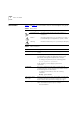
Switch 3300 SM — Front View Detail 13 Switch 3300 SM — Front View Detail Figure 1 Switch 3300 SM — front view 6x 1x 13x 10BASE-T / 100BASE-TX 12x 7x 24x 18x 19x 10BASE-T / 100BASE-TX Ports 1000BASE-SX 1 2 7 8 9 10 11 12 Status 3 4 13 14 15 16 17 18 19 20 21 22 23 24 Packet 13 14 15 16 17 18 19 20 21 22 23 24 Status 5 7 6 8 2 3 4 5 6 7 8 9 10 11 12 1 2 3 4 5 6 Packet Port Status LEDs 1000BASE-SX Port 10BASE-T/ 100BASE-TX Ports Unit green = enabled, link OK flashing green
CHAPTER 1: INTRODUCING THE SWITCH 3300 SM Table 3 LED behavior LED Color Indicates Port Status LEDs Packet Status Yellow Packets are being transmitted/received on the port. Off No packets are being transmitted/received on the port. Green A link is present, and the port is enabled. Green flashing A link is present, but the port is disabled. Off No link is present.
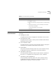
Switch 3300 SM — Rear View Detail 15 Switch 3300 SM — Rear View Detail Figure 2 Switch 3300 SM — rear view Unit Information Label Switch 3300 SM 24 Port 3C16987 MAC Addr: XXXXXXXXXX Serial XXXXXXXXXXXX Console (max) 19200,8,1,N Matrix Port Power Socket Redundant Power System Socket Unit Information Label Console Port Matrix Port This label shows the following: ■ The 3Com product name of the Switch ■ The 3Com 3C number of the Switch ■ The unique MAC address (Ethernet address) of the Switch ■
CHAPTER 1: INTRODUCING THE SWITCH 3300 SM Console Port Matrix Port The console port allows you to connect a terminal and perform remote or local out-of-band management. The console port uses standard null modem cable and is set to auto-baud, 8 data bits, no parity and 1 stop bit.
Network Configuration Examples 17 Network Configuration Examples The following illustrations show some examples of how the Switch can be used in your network. Switch 3300 SM as a Segmentation Switch The example in Figure 3 shows how a Switch 3300 SM stack can segment a network of shared 10Mbps,100Mbps and 1000Mbps connections. There is a 10/100 shared segment on each floor, and these segments are connected to the Switch which is positioned in the basement.
CHAPTER 1: INTRODUCING THE SWITCH 3300 SM Switch 3300 SM as a Collapsed Backbone Switch The example in Figure 4 shows how a Switch 3300 SM stack can act as a backbone for both shared and switched network segments.
Network Configuration Examples Switch 3300 SM as a Desktop Switch 19 The example in Figure 5 shows how a Switch 3300 SM can be used, within a stack, for a group of users that require dedicated 10Mbps or 100Mbps connections to the desktop. The 3300 SM Switches provide a Gigabit Ethernet connection to a SuperStack II Switch 9300 in the basement and to a local server.
CHAPTER 1: INTRODUCING THE SWITCH 3300 SM Configuration Rules for Fast Ethernet The topology rules for 100Mbps Fast Ethernet are slightly different to those for 10Mbps Ethernet. Figure 6 illustrates the key topology rules and provides examples of how they allow for large-scale Fast Ethernet networks.
Configuration Rules with Full Duplex 21 The key topology rules are: Configuration Rules with Full Duplex ■ Maximum UTP cable length is 100m (328ft) over Category 5 cable. ■ A 412m (1352ft) fiber run is allowed for connecting switch-to-switch, or endstation-to-switch, using half-duplex 100BASE-FX. ■ A total network span of 325m (1066ft) is allowed in single-repeater topologies (one hub stack per wiring closet with a fiber run to the collapsed backbone).
CHAPTER 1: INTRODUCING THE SWITCH 3300 SM Configuration Rules for Gigabit Ethernet Gigabit Ethernet is designed to run over four media: ■ Single-mode fiber optic cable, with connections up to 5km. ■ Multimode fiber optic cable, with connections up to 550m. ■ Balanced, shielded copper cabling, with connections up to 25m. ■ Category 5 cabling, with connections up to 100m.
2 INSTALLING THE SWITCH This chapter contains the information you need to install and set up the Switch. It covers the following topics: ■ Choosing a Suitable Site ■ Rack-mounting ■ Placing Units On Top of Each Other ■ Stacking Units ■ The Power-up Sequence ■ Choosing the Correct Cables ■ Solving Problems Indicated by LEDs ■ Managing the Switch WARNING: Safety Information.
CHAPTER 2: INSTALLING THE SWITCH Choosing a Suitable Site The Switch is suited for use in an office environment where it can be mounted in a standard 19-inch equipment rack, or free standing. Alternatively, the Switch can be rack-mounted in a wiring closet or equipment room. A rack-mounting kit, containing two mounting brackets and four screws, is supplied with the Switch.
Placing Units On Top of Each Other 25 Figure 7 Fitting a bracket for rack mounting 3 Insert the two screws and tighten with a suitable screwdriver. You must use the screws supplied with the mounting brackets. Damage caused to the unit by using incorrect screws invalidates your warranty. 4 Repeat steps 2 and 3 for the other side of the Switch. 5 Insert the Switch into the 19-inch rack and secure with suitable screws (not provided). Ensure that ventilation holes are not obstructed.
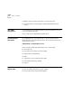
CHAPTER 2: INSTALLING THE SWITCH Stacking Units Units in the Switch 1100/3300 family can be stacked together and then treated as a single manageable unit with one IP address. The Matrix Port on the rear of the Switch allows you to connect two Switch units back-to-back. For this you need a Matrix Cable (part number 3C16965). Contact your supplier for details. The Switches in a stack are numbered 1 to 4, from the bottom up, for management purposes.
Stacking Units 27 Figure 8 A stack of two units Stacking Up To Four Units You can stack up to four Switch units using a Switch 3300 MM and the appropriate number of Matrix Cables. You need only one SuperStack II Switch 3300 MM per stack. To stack up to four Switch units: 1 Power-off all the units. 2 Arrange the units as required.
CHAPTER 2: INSTALLING THE SWITCH 4 If you use the management software of the units: ■ Ensure that all the units have the same version of management software ■ Ensure that you re-configure the stack-wide features on all the units For more information about management software, see “Managing the Switch” on page 32.
The Power-up Sequence The Power-up Sequence Connecting a Redundant Power System 29 The following sections describe how to get your Switch 3300 SM powered-up and ready for operation. You can connect a SuperStack II Advanced Redundant Power System (part number 3C16071A) to the Switch. This unit, which is also known as an ARPS, is designed to maintain the power to your Switch if a power supply failure occurs. For normal redundancy, the unit requires one Type 2 Power Module (part number 3C16074).
CHAPTER 2: INSTALLING THE SWITCH Table 5 LED colors Color State Green The Switch is powered-up and operating normally Yellow The Switch has failed its Power On Self Test. This occurs if any of the ports fail during power-up. Off The Switch is not receiving power. If there is evidence of a problem, see “Solving Problems Indicated by LEDs” on page 31. Choosing the Correct Cables All of the ports on the front of the Switch 3300 SM are configured as MDIX (cross-over).
Solving Problems Indicated by LEDs Solving Problems Indicated by LEDs 31 If the LEDs on the Switch indicate a problem, refer to Table 6 which contains a list of problems and suggested solutions. Table 6 Problems indicated by LEDs Problem Suggested Solution A Power LED does not light Check that the power cable is firmly connected to the relevant Switch unit and to the supply outlet. If the connection is secure and there is still no power, you may have a faulty power cord.
CHAPTER 2: INSTALLING THE SWITCH Managing the Switch The Switch contains software that allows you to change and monitor the way it works. This management software is not required to get the Switch working, but if you do use it, you may improve the efficiency of the Switch and therefore improve the overall performance of your network. For information on managing the Switch using the management software, refer to the “SuperStack II Switch Management Guide”.
A SAFETY INFORMATION You must read the following safety information before carrying out any installation or removal of components, or any maintenance procedures on the Switch 3300 SM. WARNING: Warnings contain directions that you must follow for your personal safety. Follow all directions carefully. You must read the following safety information carefully before you install or remove the unit.
APPENDIX A: SAFETY INFORMATION Important Safety Information ■ Installation and removal of the unit must be carried out by qualified personnel only. ■ If installing the Switch unit in a stack with SuperStack II Hub units, the Switch 3300 SM unit must be installed below the Hub units. ■ The unit should never be connected to an A.C. outlet (power supply) without an earth (ground) connection. ■ The unit must be connected to an earthed (grounded) outlet to comply with European safety standards.
Important Safety Information 35 ■ France and Peru only: This unit cannot be powered from IT† supplies. If your supplies are of IT type, this unit must be powered by 230V (2P+T) via an isolation transformer ratio 1:1, with the secondary connection point labelled Neutral, connected directly to earth (ground). †Impédance à la terre. ■ U.K. only: The Switch 3300 SM is covered by Oftel General Approval, NS/G/12345/J/100003, for indirect connection to a public telecommunications system.
APPENDIX A: SAFETY INFORMATION L’information de Sécurité Importante ■ L'installation et la dépose de ce groupe doivent être confiés à un personnel qualifié. ■ Si vous entassez l'unité Switch avec les unités SuperStack II Hub, l'unité Switch 3300 SM doit être installée en dessous des unités Hub plus étroites. ■ L’unité ne devrait pas etre branchee a une prise de courant C.A. (source de courant) sous aucun prétexte sans un branchement mise à la terre (mise à la masse).
L’information de Sécurité Importante 37 ■ L’appareil fonctionne à une tension extrêmement basse de sécurité qui est conforme à la norme CEI 950. Ces conditions ne sont maintenues que si l'équipement auquel il est raccordé fonctionne dans les mêmes conditions. ■ France et Pérou uniquement: Ce groupe ne peut pas être alimenté par un dispositif à impédance à la terre.
APPENDIX A: SAFETY INFORMATION Wichtige Sicherheitsinformat ionen ■ Die Installation und der Ausbau des Geräts darf nur durch Fachpersonal erfolgen. ■ Wenn die Switch 3300 SM Einheit in einer Stapel mit anderen SuperStack II Hub Einheiten eingebaut werden soll, muß die Switch 3300 SM Einheit unter die schmaleren Hub Einheiten eingebaut werden. ■ Das Gerät ist unter keinen umständen an einen Wechselstrom (A.C.) Netzstecker anzuschließen ohne erdungsleitung.
Wichtige Sicherheitsinformationen 39 WARNHINWEIS: Faseroptikanschlüsse - Optische Sicherheit. Niemals mit einem Vergrößerungsgerät einen Übertragungs-Laser betrachten, während dieser eingeschaltet ist. Niemals direkt auf den Faser Anschluß und auf die Faserkabelenden schauen, während diese eingeschaltet sind.
APPENDIX A: SAFETY INFORMATION
B Null Modem Cable PIN-OUTS 9-pin to RS-232 25-pin Switch 3300 SM Cable connector: 9-pin female PC-AT Serial Cable PC/Terminal Cable connector: 25-pin male/female Screen TxD RxD Ground RTS CTS Shell 3 2 5 7 8 1 3 2 7 4 20 Screen RxD TxD Ground RTS DTR DSR DCD DTR 6 1 4 5 6 8 CTS DSR DCD only required if screen always required required for handshake 9-pin to 9-pin Switch 3300 SM Cable connector: 9-pin female PC-AT Serial Port Cable connector: 9-pin female Screen DTR TxD RxD CTS Ground Shel
APPENDIX B: PIN-OUTS Modem Cable 9-pin to RS-232 25-pin Switch 3300 SM Cable connector: 9-pin female RJ45 Pin Assignments Screen TxD RxD RTS CTS DSR Shell 3 2 7 8 6 Ground DCD DTR 5 1 4 RS-232 Modem Port Cable connector: 25-pin male 1 2 3 4 5 6 7 8 20 Screen TxD RxD RTS CTS DSR Ground DCD DTR Pin assignments are identical for 10BASE-T and 100BASE-TX RJ45 connectors Table 7 Pin assignments Pin Number Signal Function 1 TxData + Transmit data 2 TxData – Transmit data 3 RxData + Receive
RJ45 Pin Assignments Table 7 Pin assignments Pin Number Signal Function Ports configured as MDIX 1 RxData + Receive Data 2 RxData – Receive Data 3 TxData + Transmit data 4 Not assigned 5 Not assigned 6 TxData – 7 Not assigned 8 Not assigned Transmit data 43
APPENDIX B: PIN-OUTS
C TECHNICAL SPECIFICATIONS Physical Dimensions Height: 43.6mm x Width: 440mm x Depth: 247.5mm Weight: 5kg (11lbs) Environmental Requirements Operating Temperature 0° to 50°C (32° to 122°F) Storage Temperature –10° to +70°C (14° to 158°F) Operating Humidity 10–95% relative humidity, non-condensing Standards EN60068 (IEC68) — various parts Safety Agency Certifications UL 1950, EN60950, CSA 22.2 No.
APPENDIX C: TECHNICAL SPECIFICATIONS Standards Supported SNMP Terminal Emulation SNMP protocol (RFC 1157) Telnet (RFC 854) MIB-II (RFC 1213) Protocols Used for Administration Bridge MIB (RFC 1493) UDP (RFC 768) Repeater MIB (RFC 1516) IP (RFC 791) VLAN MIB (RFC 1573) ICMP (RFC 792) RMON MIB (RFC 1271) TCP (RFC 793) BOOTP (RFC 951) ARP (RFC 826) TFTP (RFC 783) Year 2000 Compliance For information on Year 2000 Compliance and 3Com products, visit the 3Com Year 2000 Web page: http://www.
D TECHNICAL SUPPORT 3Com provides easy access to technical support information through a variety of services. This appendix describes these services. Information contained in this appendix is correct at time of publication. For the most recent information, 3Com recommends that you access the 3Com Corporation World Wide Web site.
APPENDIX D: TECHNICAL SUPPORT 3Com FTP Site Download drivers, patches, software, and MIBs across the Internet from the 3Com public FTP site. This service is available 24 hours a day, 7 days a week. To connect to the 3Com FTP site, enter the following information into your FTP client: ■ Hostname: ftp.3com.com ■ Username: anonymous ■ Password: You do not need a user name and password with Web browser software such as Netscape Navigator and Internet Explorer.
Support from 3Com 49 When you contact 3Com for assistance, have the following information ready: ■ Product model name, part number, and serial number ■ A list of system hardware and software, including revision levels ■ Diagnostic error messages ■ Details about recent configuration changes, if applicable Here is a list of worldwide technical telephone support numbers: Country Telephone Number Country Telephone Number Asia, Pacific Rim Australia Hong Kong India Indonesia Japan Malaysia New Zeal
APPENDIX D: TECHNICAL SUPPORT Returning Products for Repair Before you send a product directly to 3Com for repair, you must first obtain an authorization number. Products sent to 3Com without authorization numbers will be returned to the sender unopened, at the sender’s expense.
GLOSSARY 10BASE-T The IEEE specification for 10Mbps Ethernet over Category 3, 4 or 5 twisted pair cable. 100BASE-FX The IEEE specification for 100Mbps Fast Ethernet over fiber-optic cable. 100BASE-TX The IEEE specification for 100Mbps Fast Ethernet over Category 5 twisted-pair cable. 1000BASE-SX 1000BASE-T The IEEE specification for 1000Mbps Gigabit Ethernet over fiber-optic cable. The IEEE specification for 1000Mbps Gigabit Ethernet over Category 5 twisted-pair cable.
GLOSSARY information to forward packets based on their destination address. This process is known as filtering. broadcast A packet sent to all devices on a network. broadcast storm Multiple simultaneous broadcasts that typically absorb all the available network bandwidth and can cause a network to fail. Broadcast storms can be due to faulty network devices. collision A term used to describe two colliding packets in an Ethernet network.
GLOSSARY 53 full duplex A system that allows packets to be transmitted and received at the same time and, in effect, doubles the potential throughput of a link. half duplex A system that allows packets to transmitted and received, but not at the same time. Contrast with full duplex. hub A device that regenerates LAN traffic so that the transmission distance of that signal can be extended.
GLOSSARY loop An event that occurs when two network devices are connected by more than one path, thereby causing packets to repeatedly cycle around the network and not reach their destination. MAC Media Access Control. A protocol specified by the IEEE for determining which devices have access to a network at any one time. MAC address Media Access Control address; also called hardware or physical address. A layer 2 address associated with a particular network device.
GLOSSARY server SLIP SNMP stack STP switch Switch Database TCP/IP 55 A computer in a network that is shared by multiple endstations. Servers provide endstations with access to shared network services such as computer files and printer queues. Serial Line Internet Protocol. A protocol that allows IP to run over a serial line (console port) connection. Simple Network Management Protocol. The current IETF standard protocol for managing devices on an TCP/IP network.
GLOSSARY WAN Wide Area Network. A communications network that covers a wide area. A WAN can cover a large geographic area, and may contain several LANs within it.
INDEX Numbers I 1000BASE-SX 13 10BASE-T/100BASE-TX ports 13 3C number 15 3Com Knowledgebase Web Services 47 3Com URL 47 3ComFacts 48 installing the Switch 23 prerequisites 24 A auto-negotiating ports 13 C cable choosing the correct 30 Matrix 16 maximum length 13, 21, 22 pin-outs 41 console port 16 conventions notice icons, About This Guide 8 text, About This Guide 8 cross-over configuration 13, 30 L LEDs 13 Light Emitting Diodes.
INDEX powering-up a Switch 3300 SM 29 product name 15 R rack mounting a Switch 3300 SM 24 Redundant Power System.
3Com Corporation LIMITED WARRANTY This warranty applies to customers located in the United States, Australia, Canada (except Quebec), Ireland, New Zealand, U.K., and other English language countries, and countries for which a translation into the local language is not provided.
shipped to Customer, at 3Com's expense, not later than thirty (30) days after 3Com receives the defective product, and 3Com will retain risk of loss or damage until the item is delivered to Customer. 3Com shall not be responsible for any software, firmware, information, or memory data of Customer contained in, stored on, or integrated with any products returned to 3Com for repair, whether under warranty or not. Dead- or Defective-on-Arrival.
LIMITATION OF LIABILITY TO THE FULL EXTENT ALLOWED BY LAW, 3COM ALSO EXCLUDES FOR ITSELF AND ITS SUPPLIERS ANY LIABILITY, WHETHER BASED IN CONTRACT OR TORT (INCLUDING NEGLIGENCE), FOR INCIDENTAL, CONSEQUENTIAL, INDIRECT, SPECIAL, OR PUNITIVE DAMAGES OF ANY KIND, OR FOR LOSS OF REVENUE OR PROFITS, LOSS OF BUSINESS, LOSS OF INFORMATION OR DATA, OR OTHER FINANCIAL LOSS ARISING OUT OF OR IN CONNECTION WITH THE SALE, INSTALLATION, MAINTENANCE, USE, PERFORMANCE, FAILURE, OR INTERRUPTION OF ITS PRODUCTS, EVEN IF
EMC STATEMENTS FCC STATEMENT This equipment has been tested and found to comply with the limits for a Class A digital device, pursuant to part 15 of the FCC rules. These limits are designed to provide reasonable protection against harmful interference when the equipment is operated in a commercial environment. This equipment generates, uses and can radiate radio frequency energy and, if not installed and used in accordance with the instructions, may cause harmful interference to radio communications.