SuperStack II Switch 3900 Getting Started Guide ® ® http://www.3com.com/ Part No.
3Com Corporation ■ 5400 Bayfront Plaza Copyright © 1998, 3Com Corporation. All rights reserved. No part of this documentation may be reproduced in any form or by any means or used to make any derivative work (such as translation, transformation, or adaptation) without written permission from 3Com Corporation.
EMC DIRECTIVE COMPLIANCE TRADEMARKS This equipment was tested and found to conform to the Council Directive 89/336/EEC for electromagnetic compatibility. Conformity with this Directive is based upon compliance with the following harmonized standards: Unless otherwise indicated, 3Com registered trademarks are registered in the United States and may or may not be registered in other countries.
CONTENTS 2 ABOUT THIS GUIDE Introduction 1 Finding Specific Information in This Guide Conventions 2 SuperStack II Switch 3900 Documentation Paper Documents 3 Documents on CD-ROM 4 Related Publications 4 Documentation Comments 4 Year 2000 Compliance 5 1 Before You Begin 2-1 Installing the System on a Table Top or in a Free-Standing Stack 2-2 Installing the System in a Distribution Rack 2-3 Preparing the System and Rack 2-3 Mounting the System into a Distribution Rack 2-5 1 3 3 1-4 4 1-6 CABLING SWIT
Power Up 4-2 To Power the Switch 3900 with the RPS 4-2 To Power the Switch 3900 from the Wall Receptacle 4-2 Power-up Diagnostics 4-2 System Diagnostics 4-3 Power LED Activity 4-3 Fault LED Activity 4-3 Ethernet Port Diagnostics 4-3 Packet LED Activity 4-3 Status LED Activity 4-3 System and Port Status LEDs 4-4 System Checks 4-5 Next Step: Software Configuration 4-5 A SYSTEM SPECIFICATIONS B SITE REQUIREMENTS AND SAFETY CODES General Safety Requirements B-1 Wiring Closet Recommendations B-1 Distribution
ABOUT THIS GUIDE Introduction Your SuperStack II Switch 3900 Getting Started Guide provides all the information that you need to set up your SuperStack® II Switch 3900 system and get it operating in your network. This guide provides an overview of your system and step-by-step procedures for planning your configuration, installing your system, cabling, powering up, configuring, and troubleshooting.
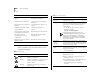
2 ABOUT THIS GUIDE For information on Turn to Deciding how to manage your system “How Do You Want to Manage the System?” on page 5-1 Setting the Console port baud “Setting the Console Port Baud” on page 5-3 Configuring the IP management interface “Configuring the IP Interface” on page 5-3 Troubleshooting hardware and software problems “Diagnosing Problems” on page 6-1 Complying with environmental and compliance specifications Appendix A: System Specifications Checking your site for environment
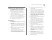
SuperStack II Switch 3900 Documentation SuperStack II Switch 3900 Documentation ■ The following documents comprise the SuperStack II Switch 3900 documentation set. Documents are shipped with your system in one of two forms: ■ ■ Paper documents that are shipped with your system or with optional components. They are listed in the next section. ■ ■ SuperStack II Switch 3900 and 9300 Unpacking Instructions How to unpack your Switch 3900 system.
4 ABOUT THIS GUIDE Documents on CD-ROM ■ The compact disc that comes with your system contains these documents: ■ Online versions of the paper documents that are shipped with your system and its components ■ SuperStack II Switch 3900 and 9300 Administration Guide ■ ■ Depending on how you install and manage your system, several related documents can provide helpful information: ■ SNMP Network Manager documents The Switch 3900 uses SNMP (Simple Network Management Protocol), which can be accessed by
Year 2000 Compliance Year 2000 Compliance For information on Year 2000 compliance and 3Com products, visit the 3Com Year 2000 Web page: http://www.3com.com/products/yr2000.
1 SWITCH 3900 SYSTEM AND SETUP OVERVIEW The Switch 3900 family consists of two models: This chapter contains: ® ■ An overview of 3Com’s SuperStack II Switch 3900 and how it provides solutions for your network ■ A description of the major features and components of the system ■ ■ 3C39024 — The 24-port 10/100BASE-TX switch, with up to three Gigabit Ethernet links. See Figure 1-1. ■ 3C39036 — The 36-port 10/100BASE-TX switch, with up to three Gigabit Ethernet links. See Figure 1-2.
1-2 CHAPTER 1: SWITCH 3900 SYSTEM AND SETUP OVERVIEW System Overview — 24-Port Front Panel Ethernet Ports Provide 24 10/100BASE-TX (RJ-45) Ethernet ports System and Port LEDs Provide information about the system and each port Status 10/100 BASE - TX 1x 6x 13x 18x green flashing green off = enabled, link OK = disabled, link OK = link fail Power Fault 1 2 3 4 5 6 7 8 9 10 11 12 Pckt 1 2 3 4 5 6 7 8 9 10 11 12 Stat 13 14 15 16 17 18 19 20 21 22 23 24 Pckt 13 14 15 16 17 18
System Overview — 36-Port Front Panel System Overview — 36-Port Front Panel v Ethernet Ports Provide 36 10/100BASE-TX (RJ-45) Ethernet ports System and Port LEDs Provide information about the system and each port Status 10/100 BASE - TX 1x 6x 13x 18x 25x 30x green flashing green off = enabled, link OK = disabled, link OK = link fail Power Fault 1 2 3 4 5 6 7 8 9 1 2 3 4 5 6 7 8 9 10 11 12 Pckt 10 11 12 Stat 13 14 15 16 17 18 19 20 21 22 23 24 Pckt 13 14 15 16 17 18 19
1-4 CHAPTER 1: SWITCH 3900 SYSTEM AND SETUP OVERVIEW System Overview — Back Panel of Both Models Optional Gigabit Ethernet Slots Allow you to add additional Gigabit Ethernet modules Fixed Gigabit Ethernet Port Provides a 1000BASE-SX link 1000 Base SX Console Pckt Stat RPS Connector Connects to the Optional Redundant Power System Power Receptacle Figure 1-3 Back Panel of the 24-Port and 36-Port SuperStack II Switch 3900 Gigabit Ethernet Port LEDs Provide information on the port status and activity
System Features and Benefits System Features and Benefits ■ The Switch 3900 is part of 3Com’s SuperStack family. To combine diverse technologies as your network grows, install the Switch 3900 in a SuperStack network. Some key features of the SuperStack II Switch 3900 system: ■ ■ ■ Autonegotiation support ■ Manageability The Switch 3900 provides full support for VLANs, Fast IP, and RMON Version 1, as well as a roving analysis port through SNMP management.
1-6 CHAPTER 1: SWITCH 3900 SYSTEM AND SETUP OVERVIEW Optional Gigabit Ethernet Modules The Switch 3900 back panel has two expansion slots that can hold optional Gigabit Ethernet modules. These modules are available in the following configurations: ■ 1000BASE-SX Module — Multimode fiber with paired SC connectors. It supports links of up to 260 meters (852 feet) over 62.5-micron multimode fiber or up to 525 meters (1722 feet) over 50-micron multimode fiber.
Network Configuration Sample Network Configuration Sample Switched Gigabit server farm Switched 100 Mb desktop systems Status 10/100 BASE - TX 1x 6x 13x 18x 25x 30x green flashing green off = enabled, link OK = disabled, link OK = link fail Power Fault 1 2 3 4 5 6 7 8 9 10 11 12 Pckt 1 2 3 4 5 6 7 8 9 10 11 12 Stat 13 14 15 16 17 18 19 20 21 22 23 24 Pckt 13 14 15 16 17 18 19 20 21 22 23 24 Stat 25 26 27 28 29 30 31 32 33 34 35 36 Pckt 25 26 27 28 29 30 31 32 33 34
INSTALLING THE SYSTEM 2 This chapter describes how to install your SuperStack® II Switch 3900 on a table top, in a free-standing stack with other SuperStack II products, or in a distribution rack. Before You Begin Before you begin this procedure, be sure to: ■ See Appendix B for site requirements.
2-2 CHAPTER 2: INSTALLING THE SYSTEM Installing the System on a Table Top or in a Free-Standing Stack Place the feet of one system into the mounting recesses of the system below it. To install the Switch 3900 system on a table top or in a free-standing stack, follow these instructions: 1 See Appendix B for site requirements. Status 10/100 BASE - TX 2 Turn the system on its side. 3 Remove the protective covering from the rubber feet.
Installing the System in a Distribution Rack 2-3 Installing the System in a Distribution Rack You can mount the system into a 19-inch distribution rack. This section describes how to prepare the system and distribution rack for installation and how to mount the system in the rack. M4 x 8 mounting screws Install your distribution rack near an easily accessible power outlet. You can power down the system only by removing the power cord from the power source.
2-4 CHAPTER 2: INSTALLING THE SYSTEM To find the top of the pattern, locate the midpoint between any two holes that are spaced 1/2 inch apart. Figure 2-3 shows the universal mounting hole pattern. Figure 2-4 illustrates the positions of two Switch 3900s, one attached to holes 1 and 4 and the other attached to holes 6 and 9. To mount only one Switch 3900, use either position.
Installing the System in a Distribution Rack Mounting the System into a Distribution Rack 2-5 4 Tighten the mounting screws. The system is now installed in the distribution rack. To mount the system into a distribution rack: 1 Carefully lift the system into place and align the appropriate holes in the mounting brackets with the designated holes in the distribution rack. See Figure 2-5. Figure 2-6 shows two Switch 3900 systems installed in a distribution rack.
3 CABLING SWITCH 3900 PORTS This chapter describes how to cable your SuperStack® II Switch 3900 system for connection to the network. It gives an overview of module cabling and describes how to cable: ■ Fast Ethernet ports ■ Gigabit Ethernet ports ■ System console port When all your Ethernet, Gigabit Ethernet, and system network connections are complete, see Chapter 4. If you are staging the system, you do not need to connect it to the network at this point.
3-2 CHAPTER 3: CABLING SWITCH 3900 PORTS Fast Ethernet Ports Your Switch 3900 has 24 or 36 10/100BASE-TX ports with RJ-45 connectors. This section contains information on cabling the 10/100BASE-TX (RJ-45) ports and pin assignments for the RJ-45 connectors. Follow these guidelines when you cable 10/100BASE-TX connectors: ■ Use two twisted-pair wires for each link. ■ Use twisted-pair wire that is 22-26 AWG (0.5 millimeter) in diameter.
Fast Ethernet Ports 10/100BASE-TX (RJ-45) Connector Pin Assignments Figure 3-1 shows the cabling of a 10/100BASE-TX (RJ-45) port. Table 3-1 provides the pin assignments for the RJ-45 connectors. Table 3-1 10/100 BASE-TX (RJ-45) Pin Assignments 10/100 BASE - TX 6x 1x 13x 18x 25x Pin No.
3-4 CHAPTER 3: CABLING SWITCH 3900 PORTS Gigabit Ethernet Ports The back panel of the Switch 3900 has one fixed Gigabit Ethernet port and slots for two optional Gigabit Ethernet modules.
Cabling the Console Port To cable a Gigabit Ethernet SC port: 1 Remove the dust covers and save them for future use. 2 Attach one male connector of the SC cable connector pair to the right side of one of the Gigabit Ethernet ports on the back panel.
3-6 CHAPTER 3: CABLING SWITCH 3900 PORTS To cable the Console port: 1 Attach the female DB-9 cable connector to the Console port’s male connector and tighten the retaining screws. 2 Attach the other end of the DB-9 cable to your terminal. Figure 3-3 shows the cabling of the Console port. You can also access the system remotely through any Ethernet port using telnet. See the SuperStack II Switch 3900 and 9300 Administration Guide.
Cabling the Console Port Console Port Pin Assignments Table 3-2 shows the DB-9 pin assignments for the Console port. Table 3-2 Console Port DB-9 Pin Assignments Pin No.
SYSTEM POWER UP 4 Optional Advanced Redundant Power System This chapter contains: SuperStack® ■ “Power Options” for the 3900 system II Switch ■ “Power Up” instructions the Switch 3900 system ■ A description of “Power-up Diagnostics” ■ A list of “System Checks” after power up For information on troubleshooting the system during power up, see Chapter 6. Power Options You have three options for how to power up your Switch 3900 system. Place the system near a power receptacle.
4-2 CHAPTER 4: SYSTEM POWER UP Power Up This section provides instructions on how to set up and plug in your system. See Chapter 3 and Chapter 5 for information about cabling and configuring the Console port. To view error messages while the system runs power-up diagnostics, connect a terminal, a workstation, or a PC with terminal emulation to the system’s Console port.
Power-up Diagnostics System Diagnostics 4-3 Ethernet Port Diagnostics This section describes the LEDs that provide information about the system as a whole. This section summarizes the information displayed by the port LEDs. Power LED Activity Packet LED Activity ■ Green — The system is powered on; the system is running or has run diagnostics. ■ No Light — The system has no power; no diagnostics are running.
4-4 CHAPTER 4: SYSTEM POWER UP System and Port Status LEDs Fault Solid or Blinking Yellow = System failed at power up Power Green = System powered on Status 30x green flashing green off = enabled, link OK = disabled, link OK = link fail Power Fault 1 2 3 4 5 6 7 8 9 10 11 12 Pckt 1 2 3 4 5 6 7 8 9 10 11 12 Stat 13 14 15 16 17 18 19 20 21 22 23 24 Pckt 13 14 15 16 17 18 19 20 21 22 23 24 Stat 25 26 27 28 29 30 31 32 33 34 35 36 Pckt 25 26 27 28 29 30 31 32 33 34 35 36 Stat 36x
System Checks System Checks After the system has successfully completed the power-up diagnostics, check the items in Table 4-1 to verify that the system is operating correctly. If you discover abnormal conditions, see Chapter 6. Table 4-1 System Power-Up Checklist Check Description Power-up error messages If there is a problem during power-up, the messages are displayed in the Administration Console connection through the Console port.
5 QUICK SETUP FOR MANAGEMENT ACCESS This chapter provides easy instructions for configuring the SuperStack® II Switch 3900 system for management access. After you decide how you want to manage your system, follow the configuration instructions for your preferred type of management access. How Do You Want to Manage the System? You can manage your system locally through a terminal connection or through the network with an IP connection. Table 5-1 describes the access mechanisms.
5-2 CHAPTER 5: QUICK SETUP FOR MANAGEMENT ACCESS Terminal Connection Direct access through the Console port is often preferred because it allows you to remain on the system during system boots. A Macintosh or PC attachment can use any terminal emulation program for connecting to the Console port. A workstation attachment under UNIX can use the emulator TIP. For more details, see the documentation that is shipped with your terminal emulation program.
Configuring the IP Interface Setting the Console Port Baud To change the baud setting of the Console port: 1 From the top level of the Administration Console, at the Select menu option prompt, enter: system 2 At the system menu, enter: Configuring the IP Interface These instructions include information on how to define an IP interface through which you can manage your Switch 3900 system.
6 TROUBLESHOOTING THE SYSTEM This chapter explains how to troubleshoot certain problems with the SuperStack® II Switch 3900 system. It covers: ■ Getting Additional Help ■ Diagnosing Problems ■ Cleaning Dirty Fiber Optic Ports and Connectors Getting Additional Help If you experience system problems that are not addressed in this chapter, contact 3Com Technical Support or your service representative.
6-2 CHAPTER 6: TROUBLESHOOTING THE SYSTEM Table 6-1 Troubleshooting Power Failures Symptom Possible Sources of the Problem Steps to Take System does not power up. ■ System is not receiving power. 1 Verify that the building’s power outlet has power. ■ Power supply malfunctioned. 2 Check that the power cord is firmly plugged into the system and either the building’s power outlet, the redundant power system, or the uninterruptible power system.
Diagnosing Problems 6-3 Table 6-3 Troubleshooting Abnormal Port LED Activity LED Status Possible Sources of the Problem Steps to Take Pckt LED does not light. Software error Check the Administration Console display. Stat LED does not light. System does not recognize a connection to the port. 1 Verify that all cables are firmly plugged into both the system’s affected port and the attached device. ■ Cable is not fully attached to the port. 2 Test for faulty cables. ■ Port cable is faulty.
6-4 CHAPTER 6: TROUBLESHOOTING THE SYSTEM Cleaning Dirty Fiber Optic Ports and Connectors Fiber optic transceivers are sensitive optical devices. Handle them carefully. If dirt collects on a fiber optic lens, the associated LED may not light. You may also notice degradation in port performance, indicated by an increase in the Link Error Rate (LER) count on a port.
A SYSTEM SPECIFICATIONS Table A-1 System Specifications for the SuperStack II Switch 3900 Stackable Switch Specifications Physical Dimensions 6.5 cm (H) x 44 cm (W) x 30.5 cm (D) 2.59 inches (H) x 17.32 inches (W) x 12.00 inches (D) Weight: 4.
A-2 APPENDIX A: SYSTEM SPECIFICATIONS Table A-2 Standards Supported by the SuperStack II Switch 3900 Standard Type RFC Supported SNMP ■ SNMP protocol (RFC 1157) ■ MIB II (RFC 1213) ■ Ethernet MIB (RFC 1284) ■ Bridge MIB (RFC 1286) Software Installation tftp (RFC 959) Terminal Emulation ■ Protocols Used for Administration telnet (RFC 854) ■ rlogin (RFC 1282) ■ UDP (RFC 768) ■ IP (RFC 791) ■ ICMP (RFC 792) ■ TCP (RFC 793) ■ ARP (RFC 826) Table A-3 LED Indicators on the SuperStac
B SITE REQUIREMENTS AND SAFETY CODES You took careful steps to plan and prepare your site for new or additional SuperStack® II Switch 3900 stackable switch systems. For your reference, this appendix summarizes the criteria that your site should meet for the Switch 3900 to operate safely and effectively. Wiring Closet Recommendations The cabling system plan at your facility probably covers most wiring closet concerns.
B-2 APPENDIX B: SITE REQUIREMENTS AND SAFETY CODES ■ Be sure that each wiring closet has a suitable ground. Ground all metal racks, enclosures, boxes, and raceways in the closet. ■ Use AC power, 15-ampere service receptacles, type N5/15 or NEMA 5-15R for 120 VAC, and the other system specifications shown in Appendix A. ■ Be especially sure to meet all system environmental requirements in Appendix A, such as ambient temperature and humidity.
Distribution Rack Requirements ■ B-3 In countries other than the United States, comply with IEC Standard 297: Dimensions of Panels and Racks. In addition, 3Com recommends that your distribution racks meet these requirements: 76 cm (30 in.) ■ Use an open style, 19-inch rack. The rack styles shown in Figure B-2 facilitate easy maintenance and provide excellent ventilation. ■ Use a rack that has the universal mounting rail hole pattern identified in IEC Standard 297.
B-4 APPENDIX B: SITE REQUIREMENTS AND SAFETY CODES Building and Electrical Codes Follow all appropriate building codes and authorities on electrical codes when planning your site and installing your cable for the Switch 3900 system. Specific building and electrical codes vary depending on your location. The following lists are provided as resources to help you to find additional information.
Building and Electrical Codes Electrical Codes ■ Authorities on electrical codes (USA only): ■ National Electrical Code (NEC) Classification — A recognized authority on safe electrical wiring. Federal, state, and local governments use NEC standards to establish their own laws, ordinances, and codes on wiring specifications.
C TECHNICAL SUPPORT 3Com provides easy access to technical support information through a variety of services. This appendix describes these services. Information contained in this appendix is correct at time of publication. For the very latest, 3Com recommends that you access the 3Com Corporation World Wide Web site.
C-2 APPENDIX C: TECHNICAL SUPPORT 3ComFacts Automated Fax Service Access by Analog Modem To reach the service by modem, set your modem to 8 data bits, no parity, and 1 stop bit. Call the telephone number nearest you: The 3ComFacts automated fax service provides technical articles, diagrams, and troubleshooting instructions on 3Com products 24 hours a day, 7 days a week.
Support from 3Com Support from 3Com If you are unable to obtain assistance from the 3Com online technical resources or from your network supplier, 3Com offers technical telephone support services. To find out more about your support options, please call the 3Com technical telephone support phone number at the location nearest you. When you contact 3Com for assistance, have the following information ready: Country Telephone Number Singapore S. Korea From anywhere in S.
C-4 APPENDIX C: TECHNICAL SUPPORT Returning Products for Repair Before you send a product directly to 3Com for repair, you must first obtain a Return Materials Authorization (RMA) number. Products sent to 3Com without RMA numbers will be returned to the sender unopened, at the sender’s expense.
INDEX Numbers C E 10/100BASE-TX cabling 3-2 connector pin assignments 3-3 1000BASE-LX module 3-4 1000BASE-SX module 3-4 3Com bulletin board service (3Com BBS) C-1 3Com FTP site C-1 3Com URL 1, C-1 3ComFacts fax service C-2 AC components Redundant Power System 4-1 Uninterruptible Power System 4-1 Administration Console accessing 5-2 configuring IP addresses 5-3 Advanced Redundant Power System (RPS) 4-1 air conditioning requirements for system B-2 audience 1 cabling 10/100BASE-TX (RJ-45) ports 3-2 1000B
2 INDEX G M Gigabit Ethernet cabling 3-4 modules 3-4 ports 3-4 management access 1-5, 5-1 management, Switch 3900 IP 5-1 modem 5-1 terminal 5-1 modem 3-5, 5-1 module fiber optic safety 3-1 modules Gigabit Ethernet 3-4 mounting brackets 2-3 mounting hole pattern 2-3 mounting rails B-3 multimode fiber safety precautions 3-1 H hardware mounting kit 2-1 humidity specifications A-1, B-2 I ICBO (building code) B-4 IEC Standard 297 B-3 impedance twisted-pair guidelines 3-2 installation distribution rack 2-3
INDEX S T U safety requirements and standards B-1 working with fiber optic cables and LEDs 3-1 SBC (Standard Building Code) B-4 SC connectors 3-4 serial line, and management access 5-1 serial port cabling 3-5 single-mode fiber safety 3-1 site planning environmental and safety requirements B-1 rack requirements B-2 wiring closet considerations B-1 SNMP agent 5-1 and Switch 3900 management 5-1 standards supported A-2 software release notes 1 stacking systems 2-1 subnet mask 5-3 Switch 3900 cabling 3-1 coo
3Com Corporation LIMITED WARRANTY HARDWARE 3Com warrants its hardware products to be free from defects in workmanship and materials, under normal use and service, for the following lengths of time from the date of purchase from 3Com or its authorized reseller: Network Interface Cards Lifetime Other hardware products *unless otherwise specified above 1 year* Spare parts and spares kits 90 days If a product does not operate as warranted above during the applicable warranty period, 3Com shall, at its opt
3COM SHALL NOT BE LIABLE UNDER THIS WARRANTY IF ITS TESTING AND EXAMINATION DISCLOSE THAT THE ALLEGED DEFECT IN THE PRODUCT DOES NOT EXIST OR WAS CAUSED BY CUSTOMER’S OR ANY THIRD PERSON'S MISUSE, NEGLECT, IMPROPER INSTALLATION OR TESTING, UNAUTHORIZED ATTEMPTS TO REPAIR OR MODIFY, OR ANY OTHER CAUSE BEYOND THE RANGE OF THE INTENDED USE, OR BY ACCIDENT, FIRE, LIGHTNING, OR OTHER HAZARD.