DUA1730-0AAA03.book Page 1 Thursday, November 17, 2005 12:17 PM SuperStack® 3 Switch 4200 Family Getting Started Guide Switch 4200 26-Port (3C17300A) Switch 4200 50-Port (3C17302A) Switch 4200 28-Port (3C17304A) http://www.3com.com/ Part No.
DUA1730-0AAA03.book Page 2 Thursday, November 17, 2005 12:17 PM 3Com Corporation 350 Campus Drive Marlborough, MA 01752-3064 Copyright © 2002, 2005 3Com Corporation. All rights reserved. No part of this documentation may be reproduced in any form or by any means or used to make any derivative work (such as translation, transformation, or adaptation) without written permission from 3Com Technologies.
DUA1730-0AAA03.
DUA1730-0AAA03.
DUA1730-0AAA03.
DUA1730-0AAA03.
DUA1730-0AAA03.book Page 7 Thursday, November 17, 2005 12:17 PM ABOUT THIS GUIDE This guide provides all the information you need to install and use a SuperStack® 3 Switch 4200 in its default state.
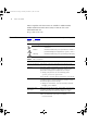
DUA1730-0AAA03.book Page 8 Thursday, November 17, 2005 12:17 PM 8 ABOUT THIS GUIDE Most user guides and release notes are available in Adobe Acrobat Reader Portable Document Format (PDF) or HTML on the 3Com World Wide Web site: http://www.3com.com/ Conventions Table 1 and Table 2 list conventions that are used throughout this guide.
DUA1730-0AAA03.book Page 9 Thursday, November 17, 2005 12:17 PM Related Documentation 9 Table 2 Text Conventions (continued) Convention Words in italics Description Italics are used to: ■ Emphasize a point. ■ Denote a new term at the place where it is defined in the text. ■ Identify menu names, menu commands, and software button names. Examples: From the Help menu, select Contents. Click OK.
DUA1730-0AAA03.book Page 10 Thursday, November 17, 2005 12:17 PM 10 ABOUT THIS GUIDE There are other publications you may find useful, such as: ■ Documentation accompanying 3Com Network Supervisor. You can download 3Com Network Supervisor and supporting documentation from the 3Com Web site at: www.3com.
DUA1730-0AAA03.book Page 11 Thursday, November 17, 2005 12:17 PM 1 INTRODUCING THE SUPERSTACK 3 SWITCH 4200 FAMILY This chapter contains introductory information about the Switch 4200 Family and how it can be used in your network.
DUA1730-0AAA03.book Page 12 Thursday, November 17, 2005 12:17 PM 12 CHAPTER 1: INTRODUCING THE SUPERSTACK 3 SWITCH 4200 FAMILY About the Switch 4200 Family The Switch 4200 Family are stackable 10/100/1000 Mbps devices which consist of: ■ 24 or 48 10BASE-T/100BASE-TX ports ■ 2 10/100/1000BASE-T ports ■ 2 SFP ports (Switch 4200 28-Port only) The Switch provides high-performance workgroups with a backbone to server connection.
DUA1730-0AAA03.
DUA1730-0AAA03.book Page 14 Thursday, November 17, 2005 12:17 PM 14 CHAPTER 1: INTRODUCING THE SUPERSTACK 3 SWITCH 4200 FAMILY WARNING: RJ-45 Ports. These are shielded RJ-45 data sockets. They cannot be used as standard traditional telephone sockets, or to connect the unit to a traditional PBX or public telephone network. Only connect RJ-45 data connectors, network telephony systems, or network telephones to these sockets.
DUA1730-0AAA03.book Page 15 Thursday, November 17, 2005 12:17 PM About the Switch 4200 Series 15 negotiated with the link partner. Alternatively, auto-negotiation can be disabled and the flow control setting can be manually configured. LEDs Table 4 lists LEDs visible on the front of the Switch, and how to read their status according to color. For information on using the LEDs for problem solving, see “Solving Problems Indicated by LEDs” on page 54.
DUA1730-0AAA03.book Page 16 Thursday, November 17, 2005 12:17 PM 16 CHAPTER 1: INTRODUCING THE SUPERSTACK 3 SWITCH 4200 FAMILY LED Color Indicates Power/Self Test LED Green The Switch is powered-up and operating normally. Green flashing The Switch is either downloading software or is initializing (which includes running a Power On Self Test). Yellow The Switch has failed its Power On Self Test. Refer to Chapter 4 Solving Problems Indicated by LEDs.
DUA1730-0AAA03.
DUA1730-0AAA03.
DUA1730-0AAA03.book Page 19 Thursday, November 17, 2005 12:17 PM 2 INSTALLING THE SWITCH This chapter contains the information you need to install and set up the Switch 4200 Family. It covers the following topics: ■ ■ ■ ■ ■ ■ ■ Package Contents Choosing a Suitable Site Rack-mounting Placing Units On Top of Each Other The Power-up Sequence SFP Operation Choosing the Correct Cables WARNING: Safety Information.
DUA1730-0AAA03.book Page 20 Thursday, November 17, 2005 12:17 PM 20 CHAPTER 2: INSTALLING THE SWITCH procedura di manutenzione, leggere le informazioni di sicurezza riportate nell'Appendice A della presente guida per l'utente.
DUA1730-0AAA03.book Page 21 Thursday, November 17, 2005 12:17 PM Rack-mounting 21 If the Switch is installed in a 19-inch rack or closed assembly its local air temperature may be greater than room ambient temperature. Rack-mounting ■ The air is as free from dust as possible. ■ The switch is situated away from sources of conductive (electrical) dust, for example, laser printers. ■ The unit is installed in a clean, air conditioned environment.
DUA1730-0AAA03.book Page 22 Thursday, November 17, 2005 12:17 PM 22 CHAPTER 2: INSTALLING THE SWITCH Figure 5 Fitting a bracket for rack-mounting 3 Insert the two screws and tighten with a suitable screwdriver. You must use the screws supplied with the mounting brackets. Damage caused to the unit by using incorrect screws invalidates your warranty. 4 Repeat steps 2 and 3 for the other side of the Switch. 5 Insert the Switch into the 19-inch rack and secure with suitable screws (not provided).
DUA1730-0AAA03.book Page 23 Thursday, November 17, 2005 12:17 PM Placing Units On Top of Each Other Placing Units On Top of Each Other 23 If the Switch units are free-standing, up to eight units can be placed one on top of the other. If you are mixing a variety of SuperStack® 3 Switch and Hub units, the smaller units must be positioned at the top. If you are placing Switch units one on top of the other, you must use the self-adhesive rubber feet supplied.
DUA1730-0AAA03.book Page 24 Thursday, November 17, 2005 12:17 PM 24 CHAPTER 2: INSTALLING THE SWITCH Stack renumbering occurs when another Switch 4200 Family unit is added to the bottom of an established stack except when the stack is already 4 units high. In this instance the ‘down’ port on the bottom unit of the existing stack will be disabled and its LED will flash green. You will then not be able to use that port again until the link is lost on that port.
DUA1730-0AAA03.book Page 25 Thursday, November 17, 2005 12:17 PM SFP Operation 25 When the POST has completed, check the Power On Self Test LED to make sure that your Switch is operating correctly. Table 6 shows possible colors for the LED. Table 6 Power/Self Test LED colors Color State Green The Switch is powered-up and operating normally. Yellow The Switch has failed its Power On Self Test. Off The Switch is not receiving power. In addition, check the Unit LEDs on all Switches in the stack.
DUA1730-0AAA03.book Page 26 Thursday, November 17, 2005 12:17 PM 26 CHAPTER 2: INSTALLING THE SWITCH Inserting an SFP Transceiver To be recognized as valid, the SFP transceiver must have the following characteristics: ■ 1000BASE-SX SFP transceiver Use this transceiver to connect the Switch directly to a multimode fiber-optic cable.
DUA1730-0AAA03.book Page 27 Thursday, November 17, 2005 12:17 PM Choosing the Correct Cables 27 Figure 7 Inserting an SFP Transceiver Product label SFP port on the Switch 4200 28-Port 6 Check the LEDs on the front of the Switch to ensure that it is operating correctly. Refer to “LEDs” on page 16 for more information. Removing an SFP Transceiver If you wish to remove a transceiver (it is not necessary to power-down your Switch): 1 Disconnect the cable from the transceiver.
DUA1730-0AAA03.book Page 28 Thursday, November 17, 2005 12:17 PM 28 CHAPTER 2: INSTALLING THE SWITCH port, you need a cross-over cable. Many ports on workstations and servers are configured as MDI (straight-through). If you want to make a connection to an MDI port, you need to use a standard straight-through cable. See Table 7. 3Com recommends that you use Category 5 twisted pair cable — the maximum segment length for this type of cable is 100 m (328 ft).
DUA1730-0AAA03.book Page 29 Thursday, November 17, 2005 12:17 PM Choosing the Correct Cables 29 If you wish to connect a 1000BASE-SX LC port to a fiber port with a different type of connector, for example, SC or ST please contact your network supplier for a suitable patch cable.
DUA1730-0AAA03.
DUA1730-0AAA03.book Page 31 Thursday, November 17, 2005 12:17 PM 3 SETTING UP FOR MANAGEMENT Your Switch can operate in its default state, that is, you can install it and it will work straight away (plug-and-play). However, to make full use of the features offered by the Switch, and to change and monitor the way it works, you have to access the management software that resides on the Switch. This is known as managing the Switch.
DUA1730-0AAA03.book Page 32 Thursday, November 17, 2005 12:17 PM CHAPTER 3: SETTING UP FOR MANAGEMENT This section gives an overview of what you need to do to get your Switch set up and ready for management when it is in its default state. The whole setup process is summarised in Figure 8. Detailed procedural steps are contained in the sections that follow.
DUA1730-0AAA03.book Page 33 Thursday, November 17, 2005 12:17 PM Setting Up Overview IP Configuration 33 You can use one of the following methods to allocate IP information to your Switch (essential if you wish to manage your Switch across the network). Manual IP Configuration You can choose to configure the IP information yourself. The Switch remembers the information that you enter until you change it again or set the configuration method to Automatic.
DUA1730-0AAA03.book Page 34 Thursday, November 17, 2005 12:17 PM 34 CHAPTER 3: SETTING UP FOR MANAGEMENT However, as soon as a DHCP or BootP server is detected, the Switch will configure itself with the IP address allocated by that server. When using automatic IP configuration it is important that the IP address of the Switch is static, otherwise you will not know what the IP address is and it will be difficult to manage.
DUA1730-0AAA03.book Page 35 Thursday, November 17, 2005 12:17 PM Manually Configuring IP Information Manually Configuring IP Information Connecting to a Front Panel Port 35 You can manually configure the Switch IP information in the following ways: ■ Connecting to a front panel port — Connect a workstation using an Ethernet cable to a front panel port of the Switch. You can then manually enter IP information using the web interface or the command line interface (CLI).
DUA1730-0AAA03.book Page 36 Thursday, November 17, 2005 12:17 PM 36 CHAPTER 3: SETTING UP FOR MANAGEMENT Connecting the Workstation to the Switch 1 Connect the workstation to a front panel port using an Ethernet cable as shown in Figure 9. Figure 9 Connecting a workstation to the Switch via a front panel port To connect the cable: a Attach an RJ-45 connector at one end of the Ethernet cable to the Network Interface Card (NIC) in the workstation.
DUA1730-0AAA03.book Page 37 Thursday, November 17, 2005 12:17 PM Manually Configuring IP Information 37 If there is no response, wait for one minute then re-enter the default IP address. 3 At the login and password prompts, enter admin as your user name and press Return at the password prompt (default user name and password). If you have logged on correctly, a set of Getting Started pages are displayed. 4 The Getting Started pages allow you to enter basic setup information for the Switch.
DUA1730-0AAA03.book Page 38 Thursday, November 17, 2005 12:17 PM 38 CHAPTER 3: SETTING UP FOR MANAGEMENT top-level menu of the command line interface is displayed as shown in the example in Figure 10.
DUA1730-0AAA03.book Page 39 Thursday, November 17, 2005 12:17 PM Manually Configuring IP Information 39 Pre-requisites ■ A workstation with terminal emulation software installed, such as Microsoft Hyperterminal. This software allows you to communicate with the Switch via the console port directly, or through a modem. ■ Documentation supplied with the terminal emulation software.
DUA1730-0AAA03.book Page 40 Thursday, November 17, 2005 12:17 PM 40 CHAPTER 3: SETTING UP FOR MANAGEMENT 2 Open your terminal emulation software and configure the COM port settings to which you have connected the cable. The settings should be set to match the default settings for the Switch, which are: ■ 19,200 baud ■ 8 data bits ■ no parity ■ 1 stop bit ■ no hardware flow control Refer to the documentation that accompanies the terminal emulation software for more information.
DUA1730-0AAA03.
DUA1730-0AAA03.book Page 42 Thursday, November 17, 2005 12:17 PM 42 CHAPTER 3: SETTING UP FOR MANAGEMENT Viewing Automatically Configured IP Information Using 3Com Network Supervisor If you allow the Switch to automatically configure its own IP information you need to discover and view the IP information before you can begin to manage the Switch.
DUA1730-0AAA03.book Page 43 Thursday, November 17, 2005 12:17 PM Viewing Automatically Configured IP Information ■ 43 A suitable cable: ■ ■ A standard null modem cable — if you are connecting directly to the console port, or A standard modem cable — if you are connecting to the console port using a modem. You can find pin-out diagrams for both cables in Appendix B on page 69. ■ A Category 5 twisted pair Ethernet cable with RJ-45 connectors to connect your Switch to the network.
DUA1730-0AAA03.book Page 44 Thursday, November 17, 2005 12:17 PM 44 CHAPTER 3: SETTING UP FOR MANAGEMENT Viewing IP Information via the Console Port You are now ready to view the automatically allocated IP information using the command line interface. 1 Connect your Switch to the network using an Ethernet cable. As soon as a network connection is made the Switch begins the automatic IP configuration process. The automatic IP configuration process usually completes within one minute.
DUA1730-0AAA03.book Page 45 Thursday, November 17, 2005 12:17 PM Methods of Managing a Switch 45 prompt enter all. A summary of the automatically allocated IP information is displayed. Make a note of the Network IP Address. The initial set up of your Switch is now complete and the Switch is ready for you to set up your chosen management method. See “Methods of Managing a Switch” on page 45.
DUA1730-0AAA03.book Page 46 Thursday, November 17, 2005 12:17 PM 46 CHAPTER 3: SETTING UP FOR MANAGEMENT Figure 15 CLI management via the console port Figure 16 CLI management over the network Refer to “Setting Up Command Line Interface Management” on page 47. Web Interface Management Each Switch has an internal set of web pages that allow you to manage the Switch using a Web browser remotely over an IP network (see Figure 17).
DUA1730-0AAA03.book Page 47 Thursday, November 17, 2005 12:17 PM Setting Up Command Line Interface Management 47 Figure 18 SNMP management over the network Refer to “Setting Up SNMP Management” on page 49. Setting Up Command Line Interface Management CLI Management via the Console Port This section describes how you can set up command line interface management using a local console port connection or over the network.
DUA1730-0AAA03.book Page 48 Thursday, November 17, 2005 12:17 PM 48 CHAPTER 3: SETTING UP FOR MANAGEMENT 4 To open a Telnet session via the DOS prompt, enter the IP address of the Switch that you wish to manage in the following format: >telnet xxx.xxx.xxx.xxx (where xxx.xxx.xxx.xxx is the IP address of the Switch) If opening a Telnet session via third party software you will need to enter the IP address in the format suitable for that software.
DUA1730-0AAA03.book Page 49 Thursday, November 17, 2005 12:17 PM Setting Up SNMP Management Mozilla 1.0 49 Windows 2000 Windows XP Windows Server 2003 Red Hat Linux 9 Solaris 7/9 ✓ ✓ ✕ ✓ ✓ For the browser to operate the web interface correctly, JavaScript™ and Cascading Style Sheets must be enabled on your browser. These features are enabled on a browser by default. You will only need to enable them if you have changed your browser settings.
DUA1730-0AAA03.book Page 50 Thursday, November 17, 2005 12:17 PM 50 CHAPTER 3: SETTING UP FOR MANAGEMENT You can use the 3Com Network Supervisor application that is provided on the CD-ROM that accompanies your Switch to provide SNMP management for your Switch. If you use 3Com Network Supervisor it automatically loads the correct MIBs and necessary files onto your workstation. Pre-requisites ■ Documentation supplied with the SNMP network management application software.
DUA1730-0AAA03.book Page 51 Thursday, November 17, 2005 12:17 PM Default Users and Passwords Changing Default Passwords 51 You can change the default passwords using either: ■ The gettingStarted command on the CLI, or ■ The security device user modify command on the CLI, or ■ The Security > Device > User > Modify operation on the web interface. For more information about default users and passwords, refer to the “Superstack 3 Switch Management Interface Reference Guide” on the Switch CD-ROM.
DUA1730-0AAA03.
DUA1730-0AAA03.book Page 53 Thursday, November 17, 2005 12:17 PM 4 PROBLEM SOLVING This chapter helps you to diagnose and solve problems you may have with the operation of your Switch. There is also an explanation of IP addressing.
DUA1730-0AAA03.book Page 54 Thursday, November 17, 2005 12:17 PM 54 CHAPTER 4: PROBLEM SOLVING Solving Problems Indicated by LEDs If the LEDs on the Switch indicate a problem, refer to the list of suggested solutions below. The Power LED does not light Check that the power cable is firmly connected to the Switch and to the supply outlet. If the connection is secure and there is still no power, you may have a faulty power cord or an internal fault.
DUA1730-0AAA03.book Page 55 Thursday, November 17, 2005 12:17 PM Solving Communication Problems 55 problem, completely remove the SFP and replace it with a 3Com approved SFP. See “Approved SFP Transceivers” on page 26. Error message indicating that the SFP transceiver is faulty. To correct this problem, completely remove the SFP and then reinsert it.Alternatively, insert another identical SFP. If the problem persists, contact 3Com Technical Support.
DUA1730-0AAA03.book Page 56 Thursday, November 17, 2005 12:17 PM 56 CHAPTER 4: PROBLEM SOLVING How do you obtain a registered IP Address? The IP registration system ensures that every IP address used is unique; if you do not have a registered IP address, you may be using an identical address to someone else and your network will not operate correctly. InterNIC Registration Services is the organization responsible for supplying registered IP addresses.
DUA1730-0AAA03.book Page 57 Thursday, November 17, 2005 12:17 PM A SAFETY INFORMATION You must read the following safety information before carrying out any installation or removal of components, or any maintenance procedures on the Switch 4200 Family. WARNING: Warnings contain directions that you must follow for your personal safety. Follow all directions carefully. You must read the following safety information carefully before you install or remove the unit.
DUA1730-0AAA03.book Page 58 Thursday, November 17, 2005 12:17 PM 58 APPENDIX A: SAFETY INFORMATION Important Safety Information WARNING: Installation and removal of the unit must be carried out by qualified personnel only. WARNING: If installing the Switch 4200 Family unit in a stack with SuperStack II or SuperStack 3 units that are shallower than the 4200 Family, the Switch 4200 Family unit must be installed below the narrower units. WARNING: The unit must be earthed (grounded).
DUA1730-0AAA03.book Page 59 Thursday, November 17, 2005 12:17 PM Important Safety Information 59 WARNING: The socket outlet must be near to the unit and easily accessible. You can only remove power from the unit by disconnecting the power cord from the outlet. WARNING: This unit operates under SELV (Safety Extra Low Voltage) conditions according to IEC 950. The conditions are only maintained if the equipment to which it is connected also operates under SELV conditions.
DUA1730-0AAA03.book Page 60 Thursday, November 17, 2005 12:17 PM 60 APPENDIX A: SAFETY INFORMATION WARNING: Fiber Optic ports - Optical Safety Never look at the transmit laser while it is powered-up. Never look directly at the fiber ports and fiber cable ends when they are powered-up. WARNING: Use of controls or adjustments of performance or procedures other than those specified herein may result in hazardous laser emissions.
DUA1730-0AAA03.
DUA1730-0AAA03.book Page 62 Thursday, November 17, 2005 12:17 PM 62 APPENDIX A: SAFETY INFORMATION connexion portant l'appellation Neutre et avec raccordement direct à la terre (masse). AVERTISSEMENT: Points d’accès RJ-45. Ceux-ci sont protégés par des prises de données. Ils ne peuvent pas être utilisés comme prises de téléphone conventionnelles standard, ni pour la connection de l’unité à un réseau téléphonique central privé ou public.
DUA1730-0AAA03.book Page 63 Thursday, November 17, 2005 12:17 PM Wichtige Sicherheitsinformationen 63 VORSICHT: Das Gerät muß an eine geerdete Steckdose angeschlossen werden, die europäischen Sicherheitsnormen erfüllt. VORSICHT: Der Anschlußkabelsatz muß mit den Bestimmungen des Landes übereinstimmen, in dem er verwendet werden soll. VORSICHT: Der Gerätestecker (der Anschluß an das Gerät, nicht der Wandsteckdosenstecker) muß eine passende Konfiguration für einen Geräteeingang gemäß EN60320/IEC320 haben.
DUA1730-0AAA03.book Page 64 Thursday, November 17, 2005 12:17 PM 64 APPENDIX A: SAFETY INFORMATION VORSICHT: Faseroptikanschlüsse – Optische Sicherheit Niemals ein Übertragungslaser betrachten, während dieses eingeschaltet ist. Niemals direkt auf die Faseransnchlüsse und auf die Faserkabelenden schauen, während diese eingeschaltet sind.
DUA1730-0AAA03.book Page 65 Thursday, November 17, 2005 12:17 PM Información de seguridad importante 65 ADVERTENCIA: conjunto de cables eléctricos: debe estar homologado para el país donde se utilice: EE.UU. y Canadá ■ El conjunto de cables debe estar homologado por UL y tener la certificación CSA. ■ La especificación mínima del cable flexible es: ■ Nº 18 AWG ■ Tipo SV o SJ ■ Tres conductores ■ El conjunto de cables debe tener una capacidad de corriente nominal de al menos 10 A.
DUA1730-0AAA03.book Page 66 Thursday, November 17, 2005 12:17 PM 66 APPENDIX A: SAFETY INFORMATION ADVERTENCIA: sólo para Francia y Perú: esta unidad no puede recibir corriente de fuentes IT†. Si las fuentes de suministro de corriente son de tipo IT, esta unidad debe recibir 230 V (2P+T) a través de un transformador aislador con relación 1:1, con el punto de conexión secundario etiquetado como neutro conectado directamente a tierra. †Impédance à la terre. ADVERTENCIA: puertos RJ-45.
DUA1730-0AAA03.book Page 67 Thursday, November 17, 2005 12:17 PM Importanti informazioni di sicurezza 67 AVVERTENZA: L'unità deve disporre di messa a terra. AVVERTENZA:Per rispettare gli standard di sicurezza, è necessario collegare l'unità a una fonte di alimentazione dotata di messa a terra. AVVERTENZA: set dei cavi di alimentazione Deve essere approvato per il paese in cui viene utilizzato.
DUA1730-0AAA03.book Page 68 Thursday, November 17, 2005 12:17 PM 68 APPENDIX A: SAFETY INFORMATION mantenute solo se anche l'apparecchiatura a cui è collegata opera nelle stesse condizioni. AVVERTENZA: solo per Francia e Perù. Questa unità non può ricevere alimentazione di tipo IT†.
DUA1730-0AAA03.
DUA1730-0AAA03.book Page 70 Thursday, November 17, 2005 12:17 PM 70 APPENDIX B: PIN-OUTS Modem Cable 9-pin to RS-232 25-pin Switch 4200 Cable connector: 9-pin female RJ-45 Pin Assignments Screen TxD RxD RTS CTS DSR Shell 3 2 7 8 6 Ground DCD DTR 5 1 4 RS-232 Modem Port Cable connector: 25-pin male 1 2 3 4 5 6 7 8 20 Screen TxD RxD RTS CTS DSR Ground DCD DTR Pin assignments for ports configured as MDI and MDIX are given in Table 10 and Table 11.
DUA1730-0AAA03.
DUA1730-0AAA03.
DUA1730-0AAA03.book Page 73 Thursday, November 17, 2005 12:17 PM C TECHNICAL SPECIFICATIONS Switch 4200 26-Port (3C17300A) Physical Dimensions Height: 44 mm (1.7 in.) x Width: 440 mm (17.3 in.) x Depth: 274 mm (10.8 in.) Weight: 2.4 kg (5.3 lbs) Environmental Requirements Operating Temperature 0 ° to 40 °C (32 ° to 104 °F) Storage Temperature –40 ° to +70 °C (-40 ° to 158 °F) Operating Humidity 10–95% relative humidity, non-condensing Standards EN60068 to 3Com schedule (Package testing: paras 2.
DUA1730-0AAA03.book Page 74 Thursday, November 17, 2005 12:17 PM 74 APPENDIX C: TECHNICAL SPECIFICATIONS Switch 4200 50-Port (3C17302A) Physical Dimensions Height: 44 mm (1.7 in.) x Width: 440 mm (17.3 in.) x Depth: 274 mm (10.8 in.) Weight: 2.83 kg (6.
DUA1730-0AAA03.book Page 75 Thursday, November 17, 2005 12:17 PM Switch 4200 28-Port (3C17304A) 75 Switch 4200 28-Port (3C17304A) Physical Dimensions Height: 44 mm (1.7 in.) x Width: 440 mm (17.3 in.) x Depth: 274 mm (10.8 in.) Weight: 2.73 kg (6.
DUA1730-0AAA03.
DUA1730-0AAA03.book Page 77 Thursday, November 17, 2005 12:17 PM D Register Your Product OBTAINING SUPPORT FOR YOUR PRODUCT Warranty and other service benefits start from the date of purchase, so it is important to register your product quickly to ensure you get full use of the warranty and other service benefits available to you. Warranty and other service benefits are enabled through product registration. Register your product at http://eSupport.3com.com/.
DUA1730-0AAA03.book Page 78 Thursday, November 17, 2005 12:17 PM 78 APPENDIX D: OBTAINING SUPPORT FOR YOUR PRODUCT Troubleshoot Online You will find support tools posted on the 3Com web site at http://www.3com.com/ 3Com Knowledgebase helps you troubleshoot 3Com products. This query-based interactive tool is located at http://knowledgebase.3com.com and contains thousands of technical solutions written by 3Com support engineers.
DUA1730-0AAA03.book Page 79 Thursday, November 17, 2005 12:17 PM Contact Us 79 To send a product directly to 3Com for repair, you must first obtain a return authorization number (RMA). Products sent to 3Com, without authorization numbers clearly marked on the outside of the package, will be returned to the sender unopened, at the sender’s expense. If your product is registered and under warranty, you can obtain an RMA number online at http://eSupport.3com.com/.
DUA1730-0AAA03.book Page 80 Thursday, November 17, 2005 12:17 PM 80 APPENDIX D: OBTAINING SUPPORT FOR YOUR PRODUCT Country Telephone Number Country Telephone Number Austria Belgium Denmark Finland France Germany Hungary Ireland Israel Italy 01 7956 7124 070 700 770 7010 7289 01080 2783 0825 809 622 01805 404 747 06800 12813 1407 3387 1800 945 3794 199 161346 Luxembourg Netherlands Norway Poland Portugal South Africa Spain Sweden Switzerland U.K.
DUA1730-0AAA03.
DUA1730-0AAA03.book Page 82 Thursday, November 17, 2005 12:17 PM 82 INDEX hardware problems 54 IP addressing 54 LEDs 54 Solving software upgrade problems 56 stack formation problems 56 product name 22 R size 73 stacking 23 unit information label 22 weight 73 system specifications 73 T troubleshooting 53 rack mounting a Switch 4200 21 S safety information English 58 French 60 German 62 Italian 66 Spanish 64 serial number of the Switch 22 serial port.
DUA1730-0AAA03.book Page 83 Thursday, November 17, 2005 12:17 PM REGULATORY NOTICES FCC STATEMENT This equipment has been tested and found to comply with the limits for a Class A digital device, pursuant to part 15 of the FCC rules. These limits are designed to provide reasonable protection against harmful interference when the equipment is operated in a commercial environment.
DUA1730-0AAA03.