SuperStack® 3 Switch Implementation Guide Generic guide for units in the SuperStack 3 Switch 4200 Series: 3C17300, 3C17302 http://www.3com.com/ Part No.
3Com Corporation 5400 Bayfront Plaza Santa Clara, California 95052-8145 Copyright © 2002, 3Com Technologies. All rights reserved. No part of this documentation may be reproduced in any form or by any means or used to make any derivative work (such as translation, transformation, or adaptation) without written permission from 3Com Technologies.
CONTENTS ABOUT THIS GUIDE Conventions 8 Related Documentation 9 Documentation Comments 9 Product Registration 10 1 SWITCH FEATURES OVERVIEW What is Management Software? 13 Switch Features Explained 13 Automatic IP Configuration 14 Port Security 14 Aggregated Links 14 Auto-negotiation 14 Multicast Filtering 15 Spanning Tree Protocol and Rapid Spanning Tree Protocol Switch Database 16 Traffic Prioritization 16 RMON 17 Broadcast Storm Control 17 VLANs 18 2 OPTIMIZING BANDWIDTH Port Features 19 Duplex 19 Fl
3 USING MULTICAST FILTERING What is an IP Multicast? 27 Benefits of Multicast 28 Multicast Filtering 28 Multicast Filtering and Your Switch IGMP Multicast Filtering 30 4 29 USING RESILIENCE FEATURES Spanning Tree Protocol (STP) 33 Rapid Spanning Tree Protocol (RSTP) 34 What is STP? 34 How STP Works 36 STP Requirements 36 STP Calculation 37 STP Configuration 38 STP Reconfiguration 38 How RSTP Differs to STP 38 STP Example 38 STP Configurations 40 Default Behavior 42 RSTP Default Behavior 42 Fast Start De
7 STATUS MONITORING AND STATISTICS RMON 53 What is RMON? 53 The RMON Groups 54 Benefits of RMON 54 RMON and the Switch 55 Alarm Events 56 The Default Alarm Settings 56 The Audit Log 57 Email Notification of Events 57 Hardware Status Monitoring 58 8 SETTING UP VIRTUAL LANS What are VLANs? 61 Benefits of VLANs 62 VLANs and Your Switch 63 The Default VLAN 63 Creating New VLANs 63 VLANs: Tagged and Untagged Membership Placing a Port in a Single VLAN 64 Connecting VLANS to Other VLANS 65 VLAN Configuration Ex
Configuration Rules with Full Duplex B 77 NETWORK CONFIGURATION EXAMPLES Simple Network Configuration Examples 80 Segmentation Switch Example 80 Collapsed Backbone Switch Example 81 Desktop Switch Example 82 Advanced Network Configuration Examples 83 Improving the Resilience of Your Network 83 Enhancing the Performance of Your Network 84 C IP ADDRESSING IP Addresses 85 Simple Overview 85 Advanced Overview 86 Subnets and Subnet Masks 88 Default Gateways 90 GLOSSARY INDEX
ABOUT THIS GUIDE This guide describes the features of the SuperStack ® 3 Switch 4200 Series and outlines how to use these features to optimize the performance of your network. This guide is intended for the system or network administrator who is responsible for configuring, using, and managing the Switches. It assumes a working knowledge of local area network (LAN) operations and familiarity with communication protocols that are used to interconnect LANs.
ABOUT THIS GUIDE Conventions Table 1 and Table 2 list conventions that are used throughout this guide.
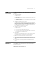
Related Documentation Related Documentation 9 In addition to this guide, each Switch documentation set includes the following: ■ Getting Started Guide This guide contains: ■ ■ ■ all the information you need to install and set up the Switch in its default state information on how to access the management software to begin managing the Switch.
ABOUT THIS GUIDE Please include the following information when contacting us: ■ Document title ■ Document part number (on the title page) ■ Page number (if appropriate) Example: ■ SuperStack 3 Switch Implementation Guide ■ Part number: DUA1730-0BAA0x ■ Page 25 Please note that we can only respond to comments and questions about 3Com product documentation at this e-mail address. Questions related to technical support or sales should be directed in the first instance to your network supplier.
I SWITCH FEATURES Chapter 1 Switch Features Overview Chapter 2 Optimizing Bandwidth Chapter 3 Using Multicast Filtering Chapter 4 Using Resilience Features Chapter 5 Using the Switch Database Chapter 6 Using Traffic Prioritization Chapter 7 Status Monitoring and Statistics Chapter 8 Setting Up Virtual LANs Chapter 9 Using Automatic IP Configuration
1 SWITCH FEATURES OVERVIEW This chapter contains introductory information about the SuperStack ® 3 Switch management software and supported features.
CHAPTER 1: SWITCH FEATURES O VERVIEW Automatic IP Configuration By default the Switch tries to configure itself with IP information without requesting user intervention. It uses the following industry standard methods to allocate the Switch IP information: ■ ■ ■ Dynamic Host Configuration Protocol (DHCP) Auto-IP — the Switch will configure itself with its default IP address 169.254.100.100 if it is operating in a standalone mode, and/or no other Switches on the network have this IP address.
Switch Features Explained 15 For details of the auto-negotiation features supported by your Switch, please refer to the Getting Started Guide that accompanies your Switch. Ports operating at 1000 Mbps only support full duplex mode. Duplex Full duplex mode allows packets to be transmitted and received simultaneously and, in effect, doubles the potential throughput of a link.
CHAPTER 1: SWITCH FEATURES O VERVIEW Spanning Tree Protocol and Rapid Spanning Tree Protocol Spanning Tree Protocol (STP) and Rapid Spanning Tree Protocol (RSTP) are bridge-based systems that makes your network more resilient to link failure and also provides protection from network loops — one of the major causes of broadcast storms.
Switch Features Explained 17 This system is compatible with the relevant sections of the IEEE 802.1D/D17 standard (incorporating IEEE 802.1p). For more information about 802.1D and traffic prioritization, see Chapter 6 “Using Traffic Prioritization”. Quality of Service Traffic prioritization can be taken one step further by using the Quality of Service (QoS) feature. Quality of Service (QoS) enables you to specify service levels for different traffic classifications.
CHAPTER 1: SWITCH FEATURES O VERVIEW VLANs A Virtual LAN (VLAN) is a flexible group of devices that can be located anywhere in a network, but which communicate as if they are on the same physical segment. With VLANs, you can segment your network without being restricted by physical connections — a limitation of traditional network design.
2 OPTIMIZING BANDWIDTH There are many ways you can optimize the bandwidth on your network and improve network performance.
CHAPTER 2: OPTIMIZING B ANDWIDTH If the devices at either end of a link do not support auto-negotiation, both ends must be manually set to full duplex or half duplex accordingly. Ports operating at 1000 Mbps support full duplex mode only. Flow Control All Switch ports support flow control, which is a mechanism that minimizes packet loss during periods of congestion on the network. Packet loss is caused by one or more devices sending traffic to an already overloaded port on the Switch.
Port Features 21 port and react accordingly. In other words, auto-negotiation may “agree” upon a configuration that the cable cannot sustain; smart auto-sensing can detect this and adjust the link accordingly. For example, smart auto-sensing can detect network problems, such as an unacceptably high error rate or a poor quality cable. If both ends of the link support 100/1000 Mbps auto-negotiation, then auto-sensing tunes the link to 100 Mbps to provide an error-free 100 Mbps connection to the network.
CHAPTER 2: OPTIMIZING B ANDWIDTH Aggregated Links Aggregated links are connections that allow devices to communicate using up to two links in parallel. Aggregated links are supported on the 10/100/1000BASE-T ports only. These parallel links provide two benefits: ■ They can potentially double the bandwidth of a connection. ■ They can provide redundancy — if one link is broken, the other link can share the traffic for that link.
Aggregated Links ■ 23 If ports of a different speed are aggregated together, the higher speed links carry the traffic. The lower speed links only carry the traffic if the higher speed links fail. ■ The aggregated link does not support security. ■ Member links must retain the same groupings at both ends of an aggregated link.
CHAPTER 2: OPTIMIZING B ANDWIDTH Traffic Distribution and Link Failure on Aggregated Links To maximize throughput, all traffic is distributed across the individual links that make up an aggregated link. Therefore, when a packet is made available for transmission down an aggregated link, a hardware-based traffic distribution mechanism determines which particular port in the link should be used; this mechanism uses the MAC address.
Aggregated Links Aggregated Link Example 25 The example shown in Figure 3 illustrates an 2 Gbps aggregated link between two Switch units. Figure 3 A 2 Gbps aggregated link between two Switch units Switch 2 Gbps Aggregated Link Switch To set up this configuration: 1 Add the 1000BASE-T ports on the upper unit to the aggregated link. 2 Add the 1000BASE-T ports on the lower unit to the aggregated link.
CHAPTER 2: OPTIMIZING B ANDWIDTH
3 USING MULTICAST FILTERING Multicast filtering improves the performance of networks that carry multicast traffic. This chapter explains multicasts, multicast filtering, and how multicast filtering can be implemented on your Switch.
CHAPTER 3: USING MULTICAST FILTERING A multicast packet is identified by the presence of a multicast group address in the destination address field of the packet’s IP header. Benefits of Multicast The benefits of using IP multicast are that it: ■ Enables the simultaneous delivery of information to many receivers in the most efficient, logical way. ■ Reduces the load on the source (for example, a server) because it does not have to produce multiple copies of the same data.
Multicast Filtering 29 Figure 4 The effect of multicast filtering Multicast Filtering and Your Switch Your Switch provides automatic multicast filtering support using IGMP (Internet Group Management Protocol) Snooping. It also supports IGMP query mode. Snooping Mode Snooping Mode allows your Switch to forward multicast packets only to the appropriate ports.
CHAPTER 3: USING MULTICAST FILTERING command will configure the Switch 4200 Series to automatically negotiate with compatible devices on VLAN 1 to become the querier. The Switch 4200 Series is compatible with any device that conforms to the IGMP v2 protocol. IGMP Multicast Filtering IGMP is the system that all IP-supporting network devices use to register endstations with multicast groups.
IGMP Multicast Filtering 31 If IGMP multicast learning is not enabled then IP multicast traffic is always forwarded, that is, it floods the network. For information about configuring IGMP functionality on an endstation, refer to the user documentation supplied with your endstation or the endstation’s Network Interface Card (NIC).
CHAPTER 3: USING MULTICAST FILTERING
4 USING RESILIENCE FEATURES Setting up resilience on your network helps protect critical links against failure, protects against network loops, and reduces network downtime to a minimum. This chapter explains the features supported by the Switch that provide resilience for your network. It covers the following topics: ■ Spanning Tree Protocol (STP) ■ Rapid Spanning Tree Protocol (RSTP) — an enhanced STP feature.
CHAPTER 4: USING R ESILIENCE FEATURES Rapid Spanning Tree Protocol (RSTP) The Rapid Spanning Tree (RSTP) is an enhanced Spanning Tree feature. RSTP implements the Spanning Tree Algorithm and Protocol, as defined in the IEEE 802.1w standard. 3Com recommends that you use the Rapid Spanning Tree Protocol feature (enabled by default) to provide optimum performance for your network and ease of use.
What is STP? 35 Figure 5 A network configuration that creates loops Figure 6 shows the result of enabling STP on the bridges in the configuration. STP detects the duplicate paths and prevents, or blocks, one of them from forwarding traffic, so this configuration will work satisfactorily. STP has determined that traffic from LAN segment 2 to LAN segment 1 can only flow through Bridges C and A, because, for example, this path has a greater bandwidth and is therefore more efficient.
CHAPTER 4: USING R ESILIENCE FEATURES Figure 7 Traffic flowing through Bridge B STP determines which is the most efficient path between each bridged segment and a specifically assigned reference point on the network. Once the most efficient path has been determined, all other paths are blocked. Therefore, in Figure 5, Figure 6, and Figure 7, STP initially determined that the path through Bridge C was the most efficient, and so blocked the path through Bridge B.
How STP Works 37 cost, the less efficient the link. Table 3 shows the default port costs for a Switch. Table 3 Default port costs Port Speed Link Type Path Cost 802.1D-1998 Path Cost 802.
CHAPTER 4: USING R ESILIENCE FEATURES STP Configuration After all the bridges on the network have agreed on the identity of the Root Bridge, and have established the other relevant parameters, each bridge is configured to forward traffic only between its Root Port and the Designated Bridge Ports for the respective network segments. All other ports are blocked, which means that they are prevented from receiving or forwarding traffic.
How STP Works 39 Figure 8 Port costs in a network ■ Bridge A has the lowest Bridge Identifier in the network, and has therefore been selected as the Root Bridge. ■ Because Bridge A is the Root Bridge, it is also the Designated Bridge for LAN segment 1. Port 1 on Bridge A is therefore selected as the Designated Bridge Port for LAN Segment 1. ■ Port 1 of Bridges B, C, X and Y have been defined as Root Ports because they are the nearest to the Root Bridge and therefore have the most efficient path.
CHAPTER 4: USING R ESILIENCE FEATURES ■ Bridge C has been selected as the Designated Bridge for LAN segment 3, because it offers the lowest Root Path Cost for LAN Segment 3: ■ ■ the route through Bridges C and B costs 200 (C to B=100, B to A=100) the route through Bridges Y and B costs 300 (Y to B=200, B to A=100). Port 2 on Bridge C is therefore selected as the Designated Bridge Port for LAN Segment 3.
How STP Works Figure 9 STP configurations 41
CHAPTER 4: USING R ESILIENCE FEATURES Default Behavior RSTP Default Behavior Fast Start Default Behavior Using STP on a Network with Multiple VLANs This section contains important information to note when using the RSTP and Fast Start features, particularly if you already have existing Switch 4200 units in your network with an older version of software. When using the RSTP feature, note that the Switch will have RSTP enabled by default.
Using STP on a Network with Multiple VLANs 43 Figure 10 Configuration that separates VLANs To avoid any VLAN subdivision, it is recommended that all inter-Switch connections are made members of all available 802.1Q VLANs to ensure connectivity at all times. For example, the connections between Switches A and B, and between Switches A and C should be 802.1Q tagged and carrying VLANs 1 and 2 to ensure connectivity. For more information about VLAN Tagging, see Chapter 8 “Setting Up Virtual LANs”.
CHAPTER 4: USING R ESILIENCE FEATURES
5 What is the Switch Database? USING THE SWITCH DATABASE The Switch Database is used by the Switch to determine where a packet should be forwarded to, and which port should transmit the packet if it is to be forwarded. The database contains a list of entries — each entry contains three items: ■ MAC (Ethernet) address information of the endstation that sends packets to the Switch. ■ Port identifier, that is the port attached to the endstation that is sending the packet.
CHAPTER 5: USING THE SWITCH DATABASE Switch Database Entry States Databases entries can have three states: ■ Learned — The Switch has placed the entry into the Switch Database when a packet was received from an endstation. Note that: ■ ■ Learned entries are removed (aged out) from the Switch Database if the Switch does not receive further packets from that endstation within a certain period of time (the aging time).
6 USING TRAFFIC PRIORITIZATION Using the traffic prioritization capabilities of your Switch allows your network traffic to be prioritized to ensure that high priority data is transmitted with minimum delay. For a list of the features supported by your Switch, please refer to the Management Quick Reference Guide that accompanies your Switch.
CHAPTER 6: USING T RAFFIC P RIORITIZATION How Traffic Prioritization Works ■ Resource planning applications — Used by organizations that require predictable and reliable access to enterprise resource planning applications such as SAP. ■ Financial applications — Used by Accounts departments that need immediate access to large files and spreadsheets.
How Traffic Prioritization Works 49 You cannot alter the mapping of the priorities. These are fixed to the traffic types as shown in Figure 11. Figure 11 IEEE 802.1D traffic types 802.1p Service levels Best effort 0 Background 1 Spare 2 Classification Strict Priority Queue Scheduling Low Priority Queue Business Critical 3 Ingress Port Egress Port 802.1D Multimedia 4 Video 5 Voice 6 High Priority Queue Network Control 7 Figure 11 illustrates IEEE 802.
CHAPTER 6: USING T RAFFIC P RIORITIZATION Figure 12 DSCP Service Level Mapping DSCP Service levels Classification Service Level 2 Best Effort Strict Priority Queue Scheduling Low Priority Queue Service Level 3 Business Critical Ingress Port DSCP Service Level 4 Video Applications All Egress Ports Service Level 5 Voice Applications Service Level 6 Internetwork Control High Priority Queue Service Level 7 Network Control Figure 12 illustrates how DiffServ code point (DSCP) service levels are ma
Traffic Prioritization and your Switch 51 How traffic is processed to provide Quality of Service A received packet at the ingress port is checked for its DSCP and IEEE 802.1D attributes to determine the level of service that the packet should receive. 802.1D packets are categorized into the 8 traffic classes defined by IEEE 802.1D; the higher the class the higher the priority given the packet on transmission.
CHAPTER 6: USING T RAFFIC P RIORITIZATION somewhere else in the network and not in the Switch 4200. Note also that 802.1D service levels are fixed and cannot be altered. 3 Create Profiles The next step is to create a profile, which associates classifiers with service levels. 4 Apply Qos profile After a QoS profile has been created, it can be assigned to the Port(s). When the profile is assigned to the port(s), the QoS configuration defined in the profile will immediately become active.
7 STATUS MONITORING AND STATISTICS This chapter contains details of the features that assist you with status monitoring and statistics. For detailed descriptions of the web interface operations and the command line interface (CLI) commands that you require to manage the Switch please refer to the Management Interface Reference Guide supplied in HTML format on the CD-ROM that accompanies your Switch.
CHAPTER 7: STATUS MONITORING AND STATISTICS the same network as the Switch and can manage the Switch by in-band or out-of-band connections. The RMON Groups The IETF define groups of Ethernet RMON statistics. This section describes the two groups supported by the Switch 4200 Series, and details how you can use them. Alarms The Alarms group provides a mechanism for setting thresholds and sampling intervals to generate events on any RMON variable.
RMON and the Switch 55 addition, probes record the behavior of your network, so that you can analyze the causes of problems. ■ It reduces the load on the network and the management workstation Traditional network management involves a management workstation polling network devices at regular intervals to gather statistics and identify problems or trends. As network sizes and traffic levels grow, this approach places a strain on the management workstation and also generates large amounts of traffic.
CHAPTER 7: STATUS MONITORING AND STATISTICS Alarm Events You can define up to 200 alarms for the Switch. The events that you can define for each alarm and their resulting actions are listed in Table 5. Table 5 Alarm Events Event Action No action Notify only Send Trap. Notify and filter port Send Trap. Block broadcast and multicast traffic on the port. Recovers with the unfilter port event. Notify and disable port Send Trap. Turn port off. Notify and enable port Send Trap. Turn port on.
RMON and the Switch 57 Table 6 Values for the default alarm(s) The Audit Log Statistic High Threshold Low Threshold Recovery Number of errors over 10 seconds Value: 8 errors per 10 seconds Value: 8 errors per 10 seconds Action: Smart auto-sensing will reduce port speed Action: None. (Speed can only be increased upon link loss, for example by removing and replacing the cable, or by triggering the port to perform another auto-negotiation on that link.
CHAPTER 7: STATUS MONITORING AND STATISTICS You can configure the email address to which you wish the notifications to be sent. However, you cannot change the factory default notification messages for event emails. RMON traps continue to be sent, in addition to any email notifications you may receive. The events that can generate email notification are: Hardware Status Monitoring ■ Unit powers up. ■ Unit in the stack fails.
Hardware Status Monitoring 59 Figure 13 Example CLI screen text *** WARNING: Unit 1 Failure detected *** Select individual unit ‘system summary? Command for details Menu options: --------------3Com Superstack 3 Switch 4200--------------bridge - Administer bridge-wide parameters logout - Logout of the Command Line Interface physicalInterface - Administer physical interfaces protocol - Administer protocols security - Administer security system - Administer sytem-level functions trafficManagement - Administ
CHAPTER 7: STATUS MONITORING AND STATISTICS Figure 15 Example device summary web page ■ RMON Trap See “Events” on page 54 for details of this feature of your Switch. ■ RMON Event Notification. You can configure Event Notification for fan failure; refer to “Email Notification of Events” on page 57 for details of this feature of your Switch.
8 SETTING UP VIRTUAL LANS Setting up Virtual LANs (VLANs) on your Switch reduces the time and effort required by many network administration tasks, and increases the efficiency of your network. This chapter explains more about the concept of VLANs and explains how they can be implemented on your Switch.
CHAPTER 8: SETTING UP VIRTUAL LANS Figure 16 A network setup showing three VLANs Benefits of VLANs The main benefit of VLANs is that they provide a network segmentation system that is far more flexible than any traditional network. Using VLANs also provides you with three other benefits: ■ VLANs ease the movement of devices on networks With traditional networks, network administrators spend much of their time dealing with moves and changes.
VLANs and Your Switch ■ 63 VLANs help to control traffic With traditional networks, congestion can be caused by broadcast traffic that is directed to all network devices whether they require it or not. VLANs increase the efficiency of your network because each VLAN can be set up to contain only those devices that need to communicate with each other. VLANs and Your Switch Your Switch provides support for VLANs using the IEEE 802.1Q standard.
CHAPTER 8: SETTING UP VIRTUAL LANS VLANs: Tagged and Untagged Membership Your Switch supports 802.1Q VLAN tagging, a system that allows traffic for multiple VLANs to be carried on a single physical (backbone) link. When setting up VLANs you need to understand when to use untagged and tagged membership of VLANs. Quite simply, if a port is in a single VLAN it can be an untagged member but if the port needs to be a member of multiple VLANs tagged membership must be defined.
VLANs and Your Switch Connecting VLANS to Other VLANS 65 If the devices placed in a VLAN need to communicate to devices in a different LAN, each VLAN requires a connection to a router or Layer 3 switching device. Communication between VLANs can only take place if they are all connected to a routing or Layer 3 switching device.
CHAPTER 8: SETTING UP VIRTUAL LANS VLAN Configuration Examples Using Untagged Connections This section contains examples of simple VLAN configurations. It describes how to set up your switch to support simple untagged and tagged connections. The simplest VLAN operates in a small network using a single switch. In this network there is no requirement to pass traffic for multiple VLANs across a link. All traffic is handled by the single Switch and therefore untagged connections can be used.
VLAN Configuration Examples 67 2 Add ports to the VLANs Add ports 10, 11 and 12 of the Switch as untagged members to VLAN 2. Using 802.1Q Tagged Connections In a network where the VLANs are distributed amongst more than one Switch, you must use 802.1Q tagged connections so that all VLAN traffic can be passed along the links between the Switches. The example shown in Figure 19 illustrates two Switch units. Each switch has endstations and a server in VLAN 1 and VLAN 2.
CHAPTER 8: SETTING UP VIRTUAL LANS 3 Add port 12 on Switch 1 to the VLANs Add port 12 on Switch 1 as a tagged member of both VLANs 1 and 2 so that all VLAN traffic is passed over the link to Switch 2. 4 Configure the VLANs on Switch 2 Define VLAN 2. VLAN 1 is the default VLAN and already exists. 5 Add endstation ports on Switch 2 to the VLANs Place the endstation ports in the appropriate VLANs as untagged members.
9 USING AUTOMATIC IP CONFIGURATION This chapter explains more about IP addresses and how the automatic configuration option works. It covers the following topics: ■ How Your Switch Obtains IP Information ■ How Automatic IP Configuration Works ■ Important Considerations For detailed information on setting up your Switch for management, see the Getting Started Guide that accompanies your Switch.
CHAPTER 9: USING AUTOMATIC IP CONFIGURATION How Your Switch Obtains IP Information You can use one of the following methods to allocate IP information to your Switch (essential if you wish to manage your Switch across the network): ■ Automatic IP Configuration (default) — the Switch tries to configure itself with IP information.
How Automatic IP Configuration Works Automatic Process 71 To detect its IP information using the automatic configuration process, the Switch goes through the following sequence of steps: 1 The DHCP client that resides in the Switch makes up to four attempts to contact a DHCP server on the network requesting IP information from the server. The attempts are at 0, 4, 12, 28 second intervals.
CHAPTER 9: USING AUTOMATIC IP CONFIGURATION Important Considerations This section contains some important points to note when using the automatic IP configuration feature. The dynamic nature of automatically configured IP information means that a Switch may change its IP address whilst in use.
II APPENDICES AND INDEX Appendix A Configuration Rules Appendix B Network Configuration Examples Appendix C IP Addressing Glossary Index
A Configuration Rules for Gigabit Ethernet CONFIGURATION RULES Gigabit Ethernet is designed to run over several media: ■ Single-mode fiber optic cable, with connections up to 5 km (3.1 miles). Support for distances over 5 km is supported depending on the module specification. ■ Multimode fiber optic cable, with connections up to 550 m (1804 ft). ■ Category 5 cabling, with connections up to 100 m (328 ft). The different types of Gigabit Ethernet media and their specifications are detailed in Table 7.
APPENDIX A: CONFIGURATION RULES Configuration Rules for Fast Ethernet The topology rules for 100 Mbps Fast Ethernet are slightly different to those for 10 Mbps Ethernet. Figure 20 illustrates the key topology rules and provides examples of how they allow for large-scale Fast Ethernet networks. Figure 20 Fast Ethernet configuration rules The key topology rules are: ■ Maximum UTP cable length is 100 m (328 ft) over Category 5 cable.
Configuration Rules for Fast Ethernet 77 collapsed backbone). For example, a 225 m (738 ft) fiber link from a repeater to a router or switch, plus a 100 m (328 ft) UTP link from a repeater out to the endstations. Configuration Rules with Full Duplex The Switch provides full duplex support for all its ports, including Expansion Module ports. Full duplex allows packets to be transmitted and received simultaneously and, in effect, doubles the potential throughput of a link.
APPENDIX A: CONFIGURATION RULES
B NETWORK CONFIGURATION EXAMPLES This chapter contains the following sections: ■ ■ Simple Network Configuration Examples ■ Segmentation Switch Example ■ Collapsed Backbone Switch Example ■ Desktop Switch Example Advanced Network Configuration Examples ■ Improving the Resilience of Your Network ■ Enhancing the Performance of Your Network
APPENDIX B: NETWORK CONFIGURATION EXAMPLES Simple Network Configuration Examples The following illustrations show some simple examples of how the Switch 4200 family and 4900 family can be used in your network. Segmentation Switch Example The example in Figure 21 shows how a 10/100 Switch such as the Switch 4200 stack can segment a network of shared 10 Mbps and 100 Mbps connections.
Simple Network Configuration Examples Collapsed Backbone Switch Example 81 The example in Figure 22 shows how a Switch 4200 stack can act as a backbone for both shared and switched network segments.
APPENDIX B: NETWORK CONFIGURATION EXAMPLES Desktop Switch Example The example in Figure 23 shows how a Switch 4200 can be used for a group of users that require dedicated 10 Mbps or 100 Mbps connections to the desktop. The Switch 4200 stack has a 1000BASE-T Module fitted that allows it to provide a Gigabit Ethernet link to a Switch 4900 in the basement.
Advanced Network Configuration Examples Advanced Network Configuration Examples Improving the Resilience of Your Network 83 This section shows some network examples that illustrate how you can set up your network for optimum performance using some of the features supported by your Switch. Figure 24 shows how you can set up your network to improve its resilience by enabling Spanning Tree Protocol (STP).
APPENDIX B: NETWORK CONFIGURATION EXAMPLES Enhancing the Performance of Your Network Figure 25 shows how you can set your network up to enhance its performance. All ports are auto-negotiating and smart auto-sensing and will therefore pass data across the network at the optimum available speed and duplex mode. Flow control will help avoid packet loss during periods of network congestion.
C IP ADDRESSING This chapter provides some background detail on the IP information that needs to be assigned to your Switch to enable you to manage it across a network. The topics covered are: ■ IP Addresses ■ Subnets and Subnet Masks ■ Default Gateways IP addressing is a vast topic and there are white papers on the World Wide Web and publications available if you wish to learn more about IP addressing.
APPENDIX C: IP ADDRESSING 192.168.100.X (where X is a number between 1 and 254) with a subnet mask 255.255.255.0. If you are using SLIP, use the default SLIP address of 192.168.101.1 with a subnet mask of 255.255.255.0. These suggested IP addresses are part of a group of IP addresses that have been set aside specially for use “in house” only. CAUTION: If your network has a connection to the external IP network, you must apply for a registered IP address.
IP Addresses 87 Dotted Decimal Notation The actual IP address is a 32-bit number that is stored in binary format. These 32 bits are segmented into 4 groups of 8 bits — each group is referred to as a field or an octet. Decimal notation converts the value of each field into a decimal number, and the fields are separated by dots. Figure 27 Dotted Decimal Notation for IP Addresses 10011110.01100101.00001010.00100000 158.101.10.
APPENDIX C: IP ADDRESSING Subnets and Subnet Masks You can divide your IP network into sub-networks also known as subnets. Support for subnets is important because the number of bits assigned to the device part of an IP address limits the number of devices that may be addressed on any given network. For example, a Class C address is restricted to 254 devices. The IP address can also contain a subnetwork part at the beginning of the host part of the IP address.
Subnets and Subnet Masks 89 As shown in this example, the 32 bits of an IP address and subnet mask are usually written using an integer shorthand. This notation translates four consecutive 8-bit groups (octets) into four integers that range from 0 through 255. The subnet mask in the example is written as 255.255.255.0. Traditionally, subnet masks were applied to octets in their entirety.
APPENDIX C: IP ADDRESSING Table 9 Subnet Mask Notation Standard Mask Notation Network Prefix Notation 100.100.100.100 (255.0.0.0) 100.100.100.100/8 100.100.100.100 (255.255.0.0) 100.100.100.100/16 100.100.100.100 (255.255.255.0) 100.100.100.100/24 The subnet mask 255.255.255.255 is reserved as the default broadcast address. Default Gateways A gateway is a device on your network which is used to forward IP packets to a remote destination. An alternative name for a gateway is a Router.
GLOSSARY 3Com Network Supervisor 10BASE-T The 3Com network management application used to manage 3Com’s networking solutions. The IEEE specification for 10 Mbps Ethernet over Category 3, 4 or 5 twisted pair cable. 100BASE-FX The IEEE specification for 100 Mbps Fast Ethernet over fiber-optic cable. 100BASE-TX The IEEE specification for 100 Mbps Fast Ethernet over Category 5 twisted-pair cable.
GLOSSARY Fast Ethernet is 100 Mbps, and the bandwidth of Gigabit Ethernet is 1000 Mbps. baud The signalling rate of a line, that is, the number of transitions (voltage or frequency changes) made per second. Also known as line speed. BOOTP The BOOTP protocol allows you to automatically map an IP address to a given MAC address each time a device is started. In addition, the protocol can assign the subnet mask and default gateway to a device.
DHCP Dynamic Host Control Protocol. A protocol that lets you centrally manage and automate the assignment of Internet Protocol (IP) addresses in an organization's network. DNS Domain Name System. This system maps a numerical Internet Protocol (IP) address to a more meaningful and easy-to-remember name. When you need to access another device on your network, you enter the name of the device, instead of its IP address.
GLOSSARY gateway GBIC Gigabit Ethernet half duplex See router. Gigabit Interface Converter. IEEE standard 802.3z for 1000 Mbps Ethernet; it is compatible with existing 10/100 Mbps Ethernet standards. A system that allows packets to transmitted and received, but not at the same time. Contrast with full duplex. hub A device that regenerates LAN traffic so that the transmission distance of that signal can be extended.
Internet Group Management Protocol Internet Group Management Protocol (IGMP) is a protocol that runs between hosts and their immediate neighboring multicast routers. The protocol allows a host to inform its local router that it wishes to receive transmissions addressed to a specific multicast group. Based on group membership information learned from the IGMP, a router is able to determine which if any multicast traffic needs to be forwarded to each of its subnetworks.
GLOSSARY loop An event that occurs when two network devices are connected by more than one path, thereby causing packets to repeatedly cycle around the network and not reach their destination. MAC Media Access Control. A protocol specified by the IEEE for determining which devices have access to a network at any one time. MAC address Media Access Control address; also called hardware or physical address. A layer 2 address associated with a particular network device.
POST QoS Profile Power On Self Test. An internal test that a Switch carries out when it is powered-up. Consists of multiple sets of rules (classifier plus service level combinations). The QoS profile is assigned to a port(s). protocol A set of rules for communication between devices on a network. The rules dictate format, timing, sequencing and error control.
GLOSSARY standard service levels, for example, best effort, business critical, network control, and so on. SLIP Serial Line Internet Protocol. A protocol that allows IP to run over a serial line (console port) connection. SMTP Simple Mail Transfer Protocol. An IETF standard protocol used for transferring mail across a network reliably and efficiently (as defined in RFC 821). SNMP Simple Network Management Protocol. The current IETF standard protocol for managing devices on an TCP/IP network.
TCP relates to the content of the data travelling through a network — ensuring that the information sent arrives in one piece when it reaches its destination. IP relates to the address of the endstation to which data is being sent, as well as the address of the destination network. Telnet A TCP/IP application protocol that provides a virtual terminal service, letting a user log into another computer system and access a device as if the user were connected directly to the device.
GLOSSARY
INDEX Numbers 802.1D priority levels 48 traffic classification 48 802.1Q tagging 64 Fast Start 42 RSTP 42 default gateway 90 Default VLAN 63 Designated Bridge 37 Designated Bridge Port 37 DHCP 14, 70 A addresses classes 87 IP 85 aggregated links 14, 22 example 25 aging time, definition 46 alarm events 56 alarm settings, default 56 Alarms (RMON group) 54, 55 audit log 57 auto-IP 14, 70 automatic IP configuration 14, 70 auto-negotiation 14, 20 E B G bandwidth 19 BOOTP 14, 70 BPDUs.
INDEX IGMP multicast filtering 30 Internet addresses 85 InterNIC 86 IP (Internet Protocol) addresses 86 IP address 14, 70, 85 classes of 87 defined 86 derivation 86 division of network and host 86 example 88 obtaining 86 subnet mask 88 subnetwork portion 88 IP multicast addressing 27 IP routing address classes 87 L learned SDB entries 46 M MAC (Media Access Control) addresses IP address 86 manual configuration 70 masks subnet 88 Matrix (RMON group) 55 Max Age 38 multicast filtering 27 IGMP 30 multic
INDEX Root Port 37 using on a network with multiple VLANs 42 subnet mask 88 defined 88 example 88 numbering 89 subnets 88 subnetworking defined 88 subnet mask 88 sub-networks. See subnets Switch Database 45 T topology rules for Fast Ethernet 76 topology rules with full duplex 77 traffic classification 802.1D 48 traffic prioritization 47 802.1D 48 V VLANs 61 802.1Q tagging 64 benefits 62 Default 63 defining the information for 63 IEEE 802.