
Powerware Uninterruptible Power System Installation and Operator's Manual

Installation
40
Powerware
®
PrestigeSeriesInstallation andOperator’s ManualforIBMApplications (3000 VA)Uncontrolled Copy
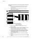
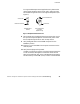
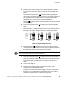
12. For the AS/400 interface, plug the AS/400 communications
cable into the serial port on the UPS rear panel. Plug the other
end of the cable into the J14 connector or the connector labeled
“UPS” on your AS/400.
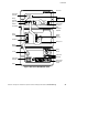
Specific locations of the J14 serial port are listed below
according to the AS/400 model:
AS/400 Models 3xx/5xx - located on the base power supply
on the back of the system unit
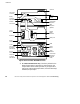
AS/400 Models 600/S10/620/S20 - on the power supply
AS/400 Models640/S30/650/S40/SB1 - on the rightside of the
regulator cage inthe back of the tower
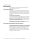
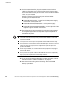
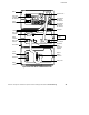
13. The equipment to be protected by the UPS should be powered
off. Plug the equipment into the power output receptacles on
the PPDM rear panel.
NOTES
Use theIEC 320-C19/C20 outputcord providedwiththe PPDMto connect the
AS/400 tothe PPDM.
You mayhaveto use theoutput cordprovidedwiththe PPDMfor 230V usage.
The AS/400line cord should be used from thePPDM input connectorto thewall
outlet(seeStep 4on page 43).Someconfigurationsrequire theinput cord
provided with PPDM.
When using thePPDM,itisrecommendedthat the equipment notbe plugged
intothe UPScabinet.
Donot protectlaser printers withthe UPS/PPDM because ofthe exceptionally
highcyclicpowerrequirementsof theheating elements.
14. If you are using a Remote Emergency Power-Off switch, follow
the instructions in “REPO Installation” on page 44.
15. Start the UPS according to the following “UPS with PPDM
Startup” procedure.