® powerware Prestige Series 3000 VA, 200-240V Installation and Operator’s Manual for IBM Applications
Requesting a Declaration of Conformity Units that are labeled with a CE mark comply with the following harmonic standards and EU directives: : : Harmonic Standards: EN 50091-1-1 and EN 50091-2 EU Directives: 73/23/EEC, Council Directive on equipment designed for use within certain voltage limits 93/68/EEC, Amending Directive 73/23/EEC 89/336/EEC, Council Directive relating to electromagnetic compatibility 92/31/EEC, Amending Directive 89/336/EEC relating to EMC The EC Declaration of Conformity is availab
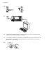
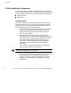
QUICK INSTALL UPS with PPDM Quick Installation 1 If you are connecting the UPS to an AS/400, the QUPSDLYTIM system value for the UPS Monitoring feature should be set. See “UPS Monitoring” on page 52 for instructions.
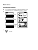
Quick Install 4 I I ON ON OFF O Battery Breaker , 21 OFF O 5 6 The UPS output voltage is factory-configured for 230V. If you need to change the output voltage, see “UPS with PPDM Startup” on page 42. 7 For the AS/400 interface, plug the AS/400 communications cable into the serial port on the UPS rear panel. Plug the other end of the cable into the J14 connector or the connector labeled “UPS” on your AS/400.
TABLE OF CONTENTS 1 Introduction . . . . . . . . . . . . . . . . . . . . . . . . . . . . . . . . . . . . . . . . . . . . . . . . . . . . 1 UPS Model and Battery Configurations . . . . . . . . . . . . . . . . . . . . . . . . . . . . . . . . . . . . . . . . . . . . . . Load Requirements . . . . . . . . . . . . . . . . . . . . . . . . . . . . . . . . . . . . . . . . . . . . . . . . . . . . . . . . . Approximate Battery Times . . . . . . . . . . . . . . . . . . . . . . . . . . . . . . . . . . . . . . . . . . .
Table of Contents UPS Communications Interface Port . . . . . . . . . . . . . . . . . . . . . . . . . . . . . . . . . . . . . . . . . . . . . . . . 64 Communications Mode Reference Chart . . . . . . . . . . . . . . . . . . . . . . . . . . . . . . . . . . . . . . . . . . . . . 65 6 Specifications . . . . . . . . . . . . . . . . . . . . . . . . . . . . . . . . . . . . . . . . . . . . . . . . . . 67 3000 VA Model Specification with PPDM . . . . . . . . . . . . . . . . . . . . . . . . . . . . . . . . . . . .
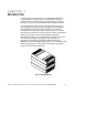
CHAPTER 1 INTRODUCTION Congratulations on the purchase of your Powerware9 Prestige Series uninterruptible power system (UPS). The Prestige UPS meets the toughest measures of superior design and manufacturing, including ISO 9001. You now own the most reliable power protection available. The Prestige 3000 provides a steady, well-regulated power supply for your computing and communications equipment, while protecting it from the frequent irregularities that are inherent in commercially available power.
Introduction UPS Model and Battery Configurations This UPS is designed to work with single-phase, three-wire, AC power sources. There are two important considerations when selecting the UPS model and battery configuration to properly safeguard your equipment: : Load requirements : Battery times Load Requirements The load is the equipment to be protected by the UPS. Select the UPS model that meets the power consumption requirements of the load in volt-amperes (VA).
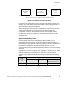
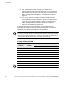
Introduction 3 COMPUTERS 3 MONITORS 200 WATTS EACH 1 AMP EACH AT 240V 3 x 200 WATTS x 1.4 = 840 VA 3 x 1 AMP x 240 = 720 VA EXTERNAL MODEM 50 VA 50 VA 840 VA + 720 VA + 50 VA = 1610 VA (Total Load Requirements) Figure 2. Volt-Amperes Calculation Example If the total load requirements of the equipment exceeds the capacity of the UPS, you must either reduce the number of pieces of equipment, or use a UPS with a larger load capacity.
Introduction 1. See “Load Requirements” on page 2 for assistance in determining the total load requirements for your UPS. Round this number up to the next Load (VA) entry in the following table, “Prestige 3000 with PPDM,” and enter the number in Figure 3. 2. In Figure 3, enter the number of battery cabinets that you have installed. Find the intersection point of the appropriate Load (VA) and number of battery cabinets in the following table, “Prestige 3000 with PPDM.
Introduction Special Symbols The following common symbols may be found on the UPS: LOAD ON - Press the button with this symbol to energize the output receptacles (Output On). LOAD OFF - Press the button with this symbol to de-energize the output receptacles (Output Off). SAFETY EARTHING TERMINAL - Indicates the primary safety ground. RISK OF ELECTRIC SHOCK - Indicates that a risk of electric shock is present and the associated warning should be observed.
Introduction This page intentionally left blank.
CHAPTER 2 SAFETY WARNINGS IMPORTANT SAFETY INSTRUCTIONS SAVE THESE INSTRUCTIONS. This manual contains important instructions that you should follow during installation of the UPS. Please read all instructions before operating the equipment and save this manual for future reference. DANGER This UPS contains LETHAL VOLTAGES. All repairs and service should be performed by AUTHORIZED SERVICE PERSONNEL ONLY. There are NO USER SERVICEABLE PARTS inside the UPS.
Safety Warnings : To comply with international standards and wiring regulations, the total equipment connected to the output of this UPS must not have an earth leakage current greater than 2.75 milliamperes. : The wall outlet must be within 2 meters of the equipment and accessible to the operator. The on/off switch on the UPS does not electrically isolate the internal parts. Unplug the input cord from the wall outlet when disconnecting the unit for long periods of time.
Safety Warnings : Batterierne bør aldrig åbnes eller skilles ad. Elektrolyt, der slipper ud, er skadelig for hud og øjne og kan være overordentlig giftig. : Brug kun den netledning, som blev leveret med UPS’en. Denne netledning er tilsluttet ifølge specifikationerne for NEC (National Electrical Code). Sørg for, at stikket, som skal bruges til UPS’en, er tilsluttet ifølge de samme specifikationer for at undgå skade på dit udstyr.
Safety Warnings Belangrijke Veiligheidsinstructies BELANGRIJKE VEILIGHEIDSINSTRUCTIES BEWAAR DEZE INSTRUCTIES DEZE HANDLEIDING BEVAT BELANGRIJKE VEILIGHEIDSINSTRUCTIES GEVAAR Deze UPS bevat LEVENSGEVAARLIJKE ELEKTRISCHE SPANNING. Alle reparaties en onderhoud dienen UITSLUITEND DOOR ERKEND SERVICEPERSONEEL te worden uitgevoerd. Er bevinden zich GEEN ONDERDELEN in de UPS die DOOR DE GEBRUIKER kunnen worden GEREPAREERD.
Safety Warnings : Verwijder de ingangsnoer niet of haal de stekker van de ingangsnoer er niet uit terwijl de UPS aan staat. Hierdoor zou de UPS en uw aangesloten apparatuur geen aardebeveiliging meer hebben. : Om aan de internationale normen en bedradingsvoorschriften te voldoen mag de gehele apparatuur die op de uitgang van deze UPS is aangesloten, geen aardlekstroom van meer dan 2,75 milliampère hebben.
Safety Warnings 12 : Tämä UPS sisältää oman energialähteen (akuston). Ulostuloliittimissä voi olla jännite, kun UPS ei ole liitettynä verkkojännitteeseen. : Älä koskaan heitä akkuja tuleen. Ne voivat räjähtää. : Älä avaa tai riko akkuja. Paljastunut elektrolyytti on vahingollinen iholle ja silmille ja voi olla erittäin myrkyllistä. : Käytä vain tämän UPS-laitteen mukana toimitettua virtakaapelia, joka on kytketty kansallisten määräysten mukaisesti.
Safety Warnings Consignes de sécurité CONSIGNES DE SÉCURITÉ IMPORTANTES CONSERVER CES INSTRUCTIONS CE MANUEL CONTIENT DES CONSIGNES DE SÉCURITÉ IMPORTANTES DANGER! Cet onduleur contient des TENSIONS MORTELLES. Toute opération d’entretien et de réparation doit être EXCLUSIVEMENT CONFIÉE A UN PERSONNEL QUALIFIÉ AGRÉÉ. AUCUNE PIÈCE RÉPARABLE PAR L’UTILISATEUR ne se trouve dans l’onduleur.
Safety Warnings : Ne pas retirer le cordon d’alimentation lorsque l’onduleur est sous tension sous peine de supprimer la mise à la terre de l’onduleur et du matériel connecté. : Afin d’être conforme aux normes et règlements internationaux de câblage, le courant de fuite à la terre de la totalité du matériel branché sur la sortie de l’onduleur ne doit pas dépasser 2,75 mA. : La prise secteur doit se trouver à moins de 2 m du matériel et être accessible à l’utilisateur.
Safety Warnings : Diese USV ist mit einer eigenen Energiequelle (Batterie) ausgestattet. An den Ausgangssteckdosen kann auch dann Spannung anliegen, wenn die USV nicht an einer Wechselspannungsquelle angeschlossen ist. : Batterien niemals verbrennen, da sie explodieren können. : Batterien nie öffnen oder anderweitig beschädigen. Der darin enthaltene Elektrolyt wirkt ätzend auf Haut und Augen. Es besteht Vergiftungsgefahr! : Nur das Netzkabel verwenden, das dieser USV beiliegt.
Safety Warnings : Für Bypass-Systeme mit festverdrahteten Eingängen muß der Überstromschutz für die Ausgangswechselstromkreise anderweitig bereitgestellt werden. : Für Bypass-Systeme mit festverdrahteten Ausgängen müssen Trennschalter für die Ausgangswechselstromkreise mit passendem Nennwert anderweitig bereitgestellt werden.
Safety Warnings : : : : : : ×ñçóéìïðïéåßôå ìüíï ôï êáëþäéï ôñïöïäïóßáò ðïõ ðáñÝ÷åôáé ìáæß ìå ôï UPS. Ôï êáëþäéï áõôü åßíáé êáôáóêåõáóìÝíï óýìöùíá ìå ôéò ðñïäéáãñáöÝò ôïõ Åèíéêïý Çëåêôñéêïý Êþäéêá (National Electrical Code) (NEC). Âåâáéùèåßôå üôé ç åíôïé÷éóìÝíç ðñßæá ðïõ ðñüêåéôáé íá ÷ñçóéìïðïéÞóåôå ìå ôï UPS åßíáé êáëùäéùìÝíç óýìöùíá ìå ôéò ßäéåò ðñïäéáãñáöÝò, þóôå íá áðïöåõ÷èåß ôõ÷üí âëÜâç óôïí åîïðëéóìü óáò.
Safety Warnings Avvisi di sicurezza IMPORTANTI ISTRUZIONI DI SICUREZZA CONSERVARE QUESTE ISTRUZIONI QUESTO MANUALE CONTIENE IMPORTANTI ISTRUZIONI DI SICUREZZA PERICOLO la TENSIONE contenuta in questo gruppo statico di continuità è LETALE. Tutte le operazioni di riparazione e di manutenzione devono essere effettuate ESCLUSIVAMENTE DA PERSONALE TECNICO AUTORIZZATO. All’interno del gruppo statico di continuità NON vi sono PARTI RIPARABILI DALL’UTENTE.
Safety Warnings : per ridurre il rischio di incendio o di scossa elettrica, installare il gruppo statico di continuità in un ambiente interno a temperatura ed umidità controllata, privo di agenti contaminanti conduttivi. La temperatura ambiente non deve superare i 40EC. Non utilizzare l’unità in prossimità di acqua o in presenza di umidità eccessiva (95% max).
Safety Warnings Viktig Sikkerhetsinformasion FARLIG Denne UPS’en inneholder LIVSFARLIGE SPENNINGER. All reparasjon og service må kun utføres av AUTORISERT SERVICEPERSONALE. BRUKERE KAN IKKE UTFØRE SERVICE PÅ NOEN AV DELENE i UPS’en. FORSIKTIG 20 : Batterier kan forårsake elektriske støt eller forbrenning på grunn av høy kortslutningsstrøm. Følg instruksene. : Batterier må fjernes på korrekt måte. Se lokale forskrifter vedrørende krav om fjerning av batterier.
Safety Warnings : UPS’ens stikkontakter for utgangsstrømforsyning er strømførende når lastbryteren ( | ) trykkes, uavhengig av strømforsyningen. : For PowerPass systemer med fastkoplete uttak, må overstrømvern for vekselstrømuttak(ene) stilles til rådighet av andre. : For PowerPass systemer med fastkoplete uttak, må passende utkoplingsbrytere for vekselstrømuttak(ene) stilles til rådighet av andre.
Safety Warnings 22 : Utilize somente o cabo de alimentação elétrica fornecido com a UPS. Este cabo foi fabricado de acordo com as especificações do IEC (International Electrical Code). Certifique-se de que a tomada de parede foi montada de acordo com estas mesmas especificações a fim de evitar danos ao seu equipamento. Na hora da instalação, verifique se foi fornecida uma proteção contra sobrecarga de circuito para a tomada de corrente alternada.
Safety Warnings Предупреждения по мерам безопасности ВАЖНЫЕ УКАЗАНИЯ ПО МЕРАМ БЕЗОПАСНОСТИ СОХРАНИТЕ ЭТИ УКАЗАНИЯ ДАННОЕ РУКОВОДСТВО СОДЕРЖИТ ВАЖНЫЕ УКАЗАНИЯ ПО МЕРАМ БЕЗОПАСНОСТИ ОПАСНО В данном ИБП имеются СМЕРТЕЛЬНО ОПАСНЫЕ НАПРЯЖЕНИЯ. Все работы по ремонту и обслуживанию должны выполняться ТОЛЬКО УПОЛНОМОЧЕННЫМ ОБСЛУЖИВАЮЩИМ ПЕРСОНАЛОМ. Внутри ИБП нет узлов, ОБСЛУЖИВАЕМЫХ ПОЛЬЗОВАТЕЛЕМ.
Safety Warnings 24 : Для снижения опасности пожара или поражения электрическим током устанавливайте ИБП в закрытом помещении с контролируемыми температурой и влажностью, в котором отсутствуют проводящие загрязняющие вещества. Температура окружающего воздуха не должна превышать 40°С. Не эксплуатируйте устройство около воды или в местах с повышенной влажностью (макс. 95%). : Не отсоединяйте сетевой шнур и не извлекайте его вилку из розетки при включенном ИБП.
Safety Warnings Advertencias de Seguridad INSTRUCCIONES DE SEGURIDAD IMPORTANTES GUARDE ESTAS INSTRUCCIONES ESTE MANUAL CONTIENE INSTRUCCIONES DE SEGURIDAD IMPORTANTES PELIGRO Este SIE contiene VOLTAJES MORTALES. Todas las reparaciones y el servicio técnico deben ser efectuados SOLAMENTE POR PERSONAL DE SERVICIO TÉCNICO AUTORIZADO. No hay NINGUNA PARTE QUE EL USUARIO PUEDA REPARAR dentro del SIE.
Safety Warnings : No retire o desenchufe el cable de entrada mientras el SIE se encuentre encendido. Esto suprime la descarga a tierra de seguridad del SIE y de los equipos conectados al SIE. : Para cumplir con los estándares internacionales y las normas de instalación, la totalidad de los equipos conectados a la salida de este SIE no debe tener una intensidad de pérdida a tierra superior a los 2,75 miliamperios.
Safety Warnings : Denna UPS-enhet har en egen energikälla (batterier). De utgående kontakterna kan vara strömförande när UPS-enheten inte är ansluten till en växelströmkälla. : Använda batterier får aldrig brännas upp. De kan explodera. : Öppna aldrig batterierna eller ta isär dem. Utsläppt elektrolyt är skadlig för hud och ögon och kan vara mycket giftig. : Använd endast den nätsladd som medföljer denna UPS-enhet. Nätsladden är kompatibel med IEC-specifikationerna (International Electrical Code).
Safety Warnings 28 Powerware® Prestige Series Installation and Operator’s Manual for IBM Applications (3000 VA) Uncontrolled Copy
Safety Warnings Powerware® Prestige Series Installation and Operator’s Manual for IBM Applications (3000 VA) Uncontrolled Copy 29
Safety Warnings 30 Powerware® Prestige Series Installation and Operator’s Manual for IBM Applications (3000 VA) Uncontrolled Copy
Safety Warnings Powerware® Prestige Series Installation and Operator’s Manual for IBM Applications (3000 VA) Uncontrolled Copy 31
Safety Warnings 32 Powerware® Prestige Series Installation and Operator’s Manual for IBM Applications (3000 VA) Uncontrolled Copy
Safety Warnings Powerware® Prestige Series Installation and Operator’s Manual for IBM Applications (3000 VA) Uncontrolled Copy 33
Safety Warnings This page intentionally left blank.
CHAPTER 3 INSTALLATION The following sections describe UPS storage requirements and the installation and startup of the UPS. Unpacking and Inspection Carefully unpack the UPS and battery cabinets, making sure to retain the packaging materials. Examine each unit carefully for any signs of damage and immediately notify your distributor if damage is present. For assistance with the IBM 9910 UPS, see Chapter 8, “AS/400 Service” on page 75.
Installation Use the following procedure to install the UPS and battery cabinets with the PPDM: 1. Place the UPS near the equipment to be protected. The UPS should be well ventilated and away from direct sunlight or other heat source. Place the UPS and battery cabinets on top of or beside the PPDM as shown in Figure 4. NOTE You can install additional battery cabinets while the UPS is operating, but confirm the UPS is not in Battery mode (see page 49).
Installation Serial Port Power Input Connector Tie Wrap Mounts Battery Connector Input Circuit Protector Power Output Receptacle UPS Cabinet REPO Receptacle (Optional) Circuit Breaker External Battery Connector Breaker Tie Battery Cord Battery Cabinet Bypass Switch Y-Cord Load Circuit Protectors Utility Input Connector Power Output Receptacles (5-15R) PPDM Figure 5.
Installation Serial Port Power Input Connector Tie Wrap Mounts Battery Connector Input Circuit Protector Power Output Receptacle UPS Cabinet REPO Receptacle (Optional) Circuit Breaker External Battery Connector Breaker Tie Battery Cord Battery Cabinet Y-Cord PPDM Power Output Receptacle (IEC 320-C19) Bypass Switch Output Protectors Neutral Ground Screw Power Output Receptacles (5-15R and 6-15R) Utility Input Connector (IEC 320-C13) Figure 6. UPS with 5-15R/6-15R PPDM Rear Panel 7.
Installation For ungrounded output neutral applications only. Remove the ground screw, rotate the ground cover until it snaps into place, and reinstall the ground screw in the ungrounded position (see Figure 7). Neutral Ground Screw Ground Cover Neutral Ground Screw Grounded Position (Default) Ground Cover Ungrounded Position (For certain applications only) Figure 7. Output Neutral Ground Screw 8.
Installation 12. For the AS/400 interface, plug the AS/400 communications cable into the serial port on the UPS rear panel. Plug the other end of the cable into the J14 connector or the connector labeled “UPS” on your AS/400.
Installation PPDM Bypass Switch Utility Input Connector (IEC 320-C20) Power Output Receptacle (IEC 320-C19) Output Breakers Power Output Receptacles (IEC 320-C13) Serial Port Y-Cord Power Input Connector Tie Wrap Mounts Battery Connector Input Circuit Protector Power Output Receptacle UPS Cabinet REPO Receptacle (Optional) Circuit Breaker External Battery Connector Breaker Tie Battery Cord Battery Cabinet Figure 8.
Installation UPS with PPDM Startup To start up the UPS: 1. If you are connecting the UPS to an AS/400, the QUPSDLYTIM system value for the UPS Monitoring feature should be set. See “UPS Monitoring” on page 52 for instructions. 2. Confirm the Bypass switch on the PPDM rear panel is in the NORMAL position. 3. Steps 4 through 8 are for changing the output voltage. The output voltage is factory-configured for 230V. If you do not need to change the output voltage, skip to Step 9.
Installation 4. Plug the input power supply cord (use the AS/400 or PPDM line cord) into the utility input connector on the PPDM rear panel. Off button while plugging the Press and hold the Output other end of the power supply cord into a grounded, three-wire, AC receptacle that has been wired in accordance with NEC specifications or national wiring rules. Release the Off button when the alarm beeps. All indicators flash Output simultaneously. 5.
Installation 10. Turn on the equipment that is connected to the UPS. 11. Press and hold the Output On button until you hear the UPS beep (approximately one second). The indicator remains lit and the Self Test indicator turns on. The front panel displays the percentage of full load being applied to the UPS. The UPS is now in Normal mode with the load online. See “Normal Mode” on page 48 for more information.
Installation 1. Place the conduit through the access hole on the junction box (see Figure 10). Connect the exposed conduit wires to the corresponding compression terminals (see the following table). Tighten the compression terminals with a screwdriver. 2. Pivot the REPO receptacle guard out of the way, plug the REPO plug/receptacle UPS connector into the REPO receptacle on the UPS rear panel and twist the connector in place (see Figure 5 on page 37).
Installation Troubleshooting Tips If you should encounter any problems during startup, see the troubleshooting chart on page 71. The battery cabinets are shipped with the batteries charged. However, batteries may lose some of the charge during shipping and storage. You can use the UPS immediately after unpacking, but it may not provide the full-rated backup time during a power failure.
CHAPTER 4 UPS OPERATION This chapter covers the operation of the UPS including front panel functions, operating modes, using the Battery Start feature, shutting down the UPS, and using the PowerPass Distribution Module. UPS Front Panel The UPS front panel has three distinct functions: : Displays the UPS operational mode (Normal, Bypass, or Battery). : Displays any alarm conditions present during operation (the indicators flash).
UPS Operation Operating Modes After you install and apply power to the UPS, the UPS filters and regulates incoming AC power, eliminating noise and voltage spikes, and provides consistent power to your equipment (see Figure 12). While power is applied to the UPS, the maintenance-free battery is automatically kept in a fully-charged condition.
UPS Operation Bypass Mode The indicator and the indicator illuminate simultaneously, indicating Bypass mode (see Figure 14). When the UPS is in Bypass mode, the load is powered by utility power. However, utility power continues to be passively filtered by the UPS. OVERLOAD SITE FAULT OVERTEMP BATTERY SELF TEST LOAD ON UNIT ON BYPASS Figure 14.
UPS Operation When shutdown is imminent, the Self Test indicator flashes. These warnings are approximate, and the actual time to shutdown may vary significantly. For approximate battery times see the table on page 4. Once these warnings are indicated, immediately complete and save your work to prevent data loss and similar difficulties. When utility power is restored after the UPS shuts down, the UPS automatically connects to the load when the startup is complete.
UPS Operation The UPS supplies power to your equipment and goes into Battery mode. The indicator remains lit and the front panel displays the percentage of battery capacity remaining to the UPS. This process should take about 15 seconds. UPS Shutdown Performing a UPS shutdown turns off the power to your protected equipment. Confirm the equipment is prepared for a power-off before shutting down the UPS.
UPS Operation UPS Monitoring UPS monitoring is a standard feature of the AS/400 operating system. QUPSDLYTIM is a timer in the AS/400 that tells the system how long to run on UPS power before shutting down. Each AS/400 system is initially assigned a default value for QUPSDLYTIM.
UPS Operation Using the PPDM The PPDM provides continuous online power for your equipment. With the PPDM, you can replace or upgrade the UPS without losing power to your equipment. Figure 16 shows the operation of the UPS with the PPDM. Utility Power In UPS Out UPS Load PPDM Battery Battery Battery Figure 16. UPS and PPDM Block Diagram Disconnecting the UPS Use the following procedure to transfer the critical load to Maintenance Bypass (AC Line operation) and remove the UPS: 1.
UPS Operation 4. Switch the circuit breaker on all battery cabinets to the OFF (O) position. 5. Disconnect the battery connector on the UPS rear panel. 6. Remove the UPS. Power Input Connector Battery Connector Power Output Receptacle UPS Cabinet Battery Circuit Breaker Battery Cabinet Bypass Switch Y-Cord PPDM Figure 17.
UPS Operation Reconnecting the UPS Use the following procedure to reinstall the UPS and transfer the critical load from Maintenance Bypass (AC Line operation) to the UPS: 1. Reconnect the battery cabinet to the battery connector on the UPS rear panel. 2. Switch the circuit breaker on all battery cabinets to the ON ( | ) position. 3. Steps 4 through 8 are for changing the output voltage. The output voltage is factory-configured for 230V. If you do not need to change the UPS output voltage, skip to Step 9.
UPS Operation 5. Press and hold the Output On button until the alarm beeps again. Two indicators, corresponding with the current setting, remain flashing. The output voltage is factory-configured for 230V. OVERLOAD SITE FAULT OVERTEMP BATTERY SELF TEST 240V 230V 220V 208V Figure 18. Output Voltage Indicators 6. Press the Output Off button to scroll through the output voltage options, top to bottom. Each time you press the button, the UPS beeps and the next two indicators flash.
CHAPTER 5 COMMUNICATION The UPS is equipped with a communications interface port that allows communication with a wide variety of external devices including: : Video or dumb terminal : Serial printer : Computer with power management or shutdown software : AS/400 systems The serial port enables you to monitor and record diagnostic data with the following communication interfaces: : Serial Communications Interface Terminal Mode Data Dump Mode Printer Mode, 2400 Baud, with Novell Contacts (default)
Communication Front Panel Communications Access Before you access the front panel, review the following configurations and note the indicator that corresponds with the communication mode. NOTE Only the Printer mode front panel options change the baud rate. Use the UPS Serial Communications Menu to select other baud rates (see page 60).
Communication To access the front panel communication options, perform the following steps: 1. If the UPS is powered on, prepare your equipment for shutdown. Off button until the long beep Press and hold the Output ceases (approximately three seconds). Unplug the UPS. Wait until all indicators turn off and then continue to the next step. Off button until 2. Plug in the UPS while pressing the Output the alarm beeps. All indicators begin flashing. 3. Press and hold the Output alarm beeps again.
Communication UPS Serial Communications Menu With the UPS Serial Communications (Main) Menu, you can view or select UPS communication modes, baud rates, and LAN configurations. To change or display the current communications configuration: 1. Connect the UPS serial port to a video monitor with a serial interface or to your computer’s serial port. If you are using OnliNet or LanSafe software, the UPS should already be connected to your computer. 2.
Communication &DWDORJ 6HULDO 9HUVLRQ &200 PRGH %DXG [ /$1 PRGH 6LWH )DXOW 'HWHFWLRQ ' & %3 & 6HUB3ULQW 1RYHOO 'LVDEOHG 1HZ &200 $6&,, 1HZ %DXG 1HZ /$1 1RYHOO 3UHVV VSDFH EDU WR FRQWLQXH NOTE Catalog #, Serial #, and Version # are all identification numbers unique to your UPS and can also be found on the UPS nameplate. 1 > Continuous Dump The UPS regularly transmits status information to the computer.
Communication 6(/(&7 /$1 &21),*85$7,21 4 ! ! ! ! ! 129(// $6 &20 /$1 0$1$*(5 &86720 &21),*85$7,21 72 48,7 7+,6 0(18 (17(5 6(/(&7,21 ! ! Select the AS400 option if you are using OnliSafe software to monitor the UPS. The Custom Configuration option has two screens: the first screen has options available for inverter shutdown, and the second screen has options available for the contact configuration.
Communication Z > Set Baud Rate allows you to select a new baud rate. The Select Baud Rate Menu displays a list of baud rate options. 4 ! ! ! ! ! ! ! 6(/(&7 %$8' 5$7( 48,7 7+,6 0(18 (17(5 6(/(&7,21 ! ! 5. To save the configuration settings, type S at the Main Menu prompt. The UPS operates and communicates under the new configuration, and defaults to these settings each time it is started. If you want to abandon the selections you have made, type Q to quit.
Communication UPS Communications Interface Port In addition to configuring the UPS for specific communication options, you must also ensure proper use of the serial port when connecting the UPS to your network or monitoring equipment. CAUTION The serial port LAN contacts are transistors and are rated at a maximum current of 50 mA and a maximum of +40 Vdc. Do not exceed these ratings or apply any negative voltage or AC voltage to these contacts; otherwise, damage may occur to your UPS.
Communication Communications Mode Reference Chart The following chart defines the UPS serial port contacts. Serial communication is not available with 3Com and AS/400 network configurations. Use only the applicable pins for the selected communication mode; otherwise, interference problems may occur. Communication Mode Function Signal Name Pin No. True Condition Serial Data to UPS RS232 TxD 2 N/A Data from UPS RS232 RxD 3 N/A Signal Ground Novell (D f l ) (Default) 7 Battery On ON.
Communication This page intentionally left blank.
CHAPTER 6 SPECIFICATIONS 3000 VA Model Specification with PPDM Input Current Output Current (Total not to exceed 2000 Watts, 3000 VA) 208:120/208 13.0A 12.50A/14.40A 208:120/240 13.0A 12.50A 240:120/240 11.3A 12.50A 208:120 13.0A 12.50A (2x5-15R)/25.00A (L5-30R) 240:120 11.3A 12.50A (2x5-15R)/25.00A (L5-30R) 220:220 12.3A 13.64A 230:230 11.7A 13.04A 240:240 11.3A 12.
Specifications Prestige 3000 UPS Technical Specifications Input Voltage Range 160 to 276 Vac Input Power Factor 0.
Specifications Part Numbers Base Equipment Machine Type Model IBM Part Number VA Watts Volts Frequency Description 9910 EP5 21H1572 3000 2100 120/208 or 120/240 50-60 Prestige 3000 Model 3000 All models include electronics module, PPDM (208V or 240V) input line cord, AS/400 communications cable, operator’s manual, and one battery pack.
Specifications Optional Accessories IBM Part Number IBM Type/Model Description 21H8444 9910-6602 Prestige 3000 Full Battery Pack Manuals IBM Order Number SC21-8379 Description Powerware Prestige Series Installation and Operator’s Manual for IBM Applications (3000 VA) Manuals may be ordered from the IBM Mechanicsburg Distribution Center.
CHAPTER 7 TROUBLESHOOTING The Prestige UPS is designed for durable, automatic operation and also alerts you whenever potential operating problems may occur. Use the following troubleshooting chart to determine the UPS alarm condition. Indicator Legend Unlit Amber Green Flashing Condition Possible Cause Action UPS does not turn on. UPS is not plugged in. Plug UPS into working outlet. Faulty wall socket. Test wall socket, repair as required. UPS input breaker is tripped.
Troubleshooting Condition Possible Cause Action Communications do not function properly. Incorrect communications cabling. Verify cable integrity (see page 64). Incorrect baud rate. Select a new baud rate (see page 63). Incorrect communication mode. Select a new communication mode (see Chapter 5). Load plug(s) not fully seated. Verify load plug(s) are fully seated. Load circuit protectors tripped. Reset load protectors. Power requirements exceed UPS capacity.
Troubleshooting Condition Possible Cause Action Weak battery while in Bypass mode. This usually indicates that the batteries need replacing or the UPS requires service. Contact your service representative. Self Test failure. UPS internal problem. The UPS may switch to Bypass mode, depending on the circumstances. Reset the UPS by pressing the Output | On button until the alarm beeps. Contact your service representative if condition persists.
Troubleshooting This page intentionally left blank.
CHAPTER 8 AS/400 SERVICE The following sections describe the methods for obtaining service for your UPS and warranty information. Warranty The warranty service on Powerware UPSs is element exchange. If the UPS becomes inoperative, the module that is inoperative will be replaced. For 3 kVA UPSs, this would either be the I/O, battery, or PowerPass Distribution Module. The process for obtaining a replacement module varies by country.
AS/400 Service Battery Warranty If, in Powerware Corporation’s opinion, the unit fails to meet published specifications and the defect is within the terms of the limited warranty (attached), the defective part(s) will be repaired or replaced at the option of Seller with no charge for replacement parts. The battery is warranted to have at least 70% of original full load capacity at the end of five years from date of installation or 66 months after manufacture, whichever comes first.
AS/400 Service Customer Responsibilities The customer is responsible for the following element exchange items: : Receiving, unpacking, and exchanging of the defective element. : Repacking the defective element in the container received with the replacement element. : Following the instructions provided for return of the defective element. IBM on-site service for the element exchange activities is available for an additional charge. United States Customer Process for Service 1.
AS/400 Service Handling of Incomplete, Damaged, or Incorrectly Shipped 9910 UPSs If the customer initially receives a 9910 UPS that is incomplete, damaged, or incorrectly shipped: 1. The customer calls IBM at 1-800-IBMSERV to report the problem. 2. An IBM representative notifies the customer of how the problem will be resolved. Canada Customer Process for Service 1. Customer calls 1-800-426-7378. 2.
AS/400 Service EMEA Customer Process for Service 1. Customer calls the local IBM office servicing account. 2. The IBM CE responds, determines the problem, and resolves the problem.
AS/400 Service Powerware Protection Guarantee Attached Equipment Protection Program Terms and Conditions Program Summary: Powerware Corporation guarantees to repair or replace (at the option of Powerware Corporation) any equipment that is damaged by AC power disturbances when said equipment is properly connected to a Powerware Corporation uninterruptible power supply (UPS) covered by the Powerware Protection Guarantee. This program provides for reimbursement of repair or replacement expenses up to $25,000.
INDEX Numeric 3Com Network Interface front panel configuration, 58 LAN Configuration Menu, 62 A Battery Fault alarm, 72 indicator, 47 Battery Mode, 49 Battery Online, indicator, 47 Battery Start, 50 Battery Test on Demand, 50 AC Line Bypass switch, 53 operation, 53 alarm silencing, 73 UPS, 72 baud rates, 60, 63 Bypass Mode, 49 Bypass switch, 37, 38, 41 C changing the output voltage, 51 Alarm Conditions Battery Fault, 72 Overload, 72 Overtemperature, 72 Self Test Failure, 73 Utility Out of Spec, 72 co
Index D Data Dump Modes, 61 diagnostics, 50 Display Configuration Screen, 61 load definition, 2 requirements, 2 LOW_BATT, 62 M Main Menu, 60 E exiting Main Menu, 63 F front panel configuring communications, 58 display functions, 47 indicators, 47 front panel configuration 3Com, 58 AS/400, 58 Novell, 58 printer mode, 58 I indicators, front panel, 47 input cord, 43, 68 82 Maintenance Bypass feature See also PowerPass Distribution Module (PPDM) activating, 53 deactivating, 55 Menu Custom LAN Configurat
Index O Operating Modes, 48 Operation Battery, 49 Bypass, 49 Normal, 48 UPS with PPDM, 53 Output Off Button, 5, 47 Maintenance Bypass feature, 35 operation, 53 power output receptacles, 37, 38, 41 rear panel, 37, 38, 41 startup, 42 utility input connector, 37, 38, 41 Printer Mode front panel configuration, 59 Main Menu configuration, 61 Output On Button, 5, 47 output voltage changing, 51 initial setting, 42 R Remote Emergency Power-Off switch.
Index Service and Support, 75 Set Baud Rate Menu, 63 shutdown, 51 Site Fault, indicator, 47 Smart Dump Mode, 61 specifications, 67 Startup Tests, 50 storage temperature, 35 Switch, Bypass, 37, 38, 41 system requirements, 2 T Terminal Modes, 61 Tests Battery (on demand), 50 Startup, 50 transistors, contact ratings, 64 troubleshooting chart, 71 tips, 46 U front panel, 47 input circuit protector, 37, 38, 41 installation, 35 operation, 47 operation with PPDM, 53 power input connector, 37, 38, 41 power outpu
Powerware® Prestige Series Installation and Operator’s Manual for IBM Applications (3000 VA) Uncontrolled Copy 85
164201134 C 86 Powerware® Prestige Series Installation and Operator’s Manual for IBM Applications (3000 VA) Uncontrolled Copy