NETBuilder II® HSSI Module Installation Guide A member of the NETBuilder® family THE PRESIDENT S ENVIRONMENT AND CONSERVATION CHALLENGE AWARD 1992 For 3Com User Group Information 1-800-NET-3Com or your local 3Com office Manual Part No. 09-0489-000 Published January, 1994. Printed in the U.S.A.
3Com Corporation 5400 Bayfront Plaza Santa Clara California 95052-8145 © 3Com Corporation, 1994. All rights reserved. No part of this manual may be reproduced in any form or by any means or used to make any derivative work (such as translation, transformation, or adaptation) without permission from 3Com Corporation.
Before You Begin This guide describes how to install, cable, maintain, and troubleshoot the High-Speed Serial Interface (HSSI) module for the NETBuilder II® base system. The information in this guide applies to the NETBuilder II 4-slot chassis and the NETBuilder II 8-slot chassis. For more information about the NETBuilder II base system installation, refer to the NETBuilder II Base System Installation Guide.
Keys When specific keys are referred to in the text, they are called out by their labels, such as “the Return key” or “the Escape key,” or they may be shown as [Return] or [Esc]. If two or more keys are to be pressed simultaneously, the keys are linked with a plus sign (+), for example: Press [Ctrl]+[Alt]+[Del]. Italics Italics are used to denote new terms or emphasis. Special Messages A special format indicates notes, cautions, and warnings. These messages are defined as follows.
Chapter 1 Installation This chapter describes how to install the HSSI module into the NETBuilder II ® base system. The HSSI module provides a single serial interface for a WAN connection in the NETBuilder II base system. It supports transmission rates up to OC1, including E3, T3, and sub-rates. NOTE: The HSSI module must be used with NETBuilder II HSSI and Single-Mode FDDI Software 6.2. For information about the software, see the NETBuilder II HSSI and SingleMode FDDI Software 6.2 Release Notes.
1-2 Installation Before Installing the HSSI Module 3. Verify that you have received all the contents. When you purchase the HSSI module, you receive the following: ■ ■ HSSI module NETBuilder II HSSI Module Installation Guide If an item is missing from an undamaged carton, contact your network supplier to secure a replacement. ule I Mod ®I HSS I e r uildetion Guid mily NETB der fa lla TBuil Insta e NE mber A me of th ation Inform roup e ser G om U -3Com om offic .S.A.
Installation 1-3 Installing the HSSI Module Installing the HSSI Module Use this procedure to install the HSSI module into the NETBuilder II base system. You will need a small flathead screwdriver. NOTE: There are two versions of the NETBuilder II 4-slot and 8-slot chassis. The older, singlewide versions of the NETBuilder II 4-slot and 8-slot chassis have two flipper ejectors for each module.
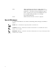
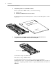
1-4 Installation Installing the HSSI Module 3. Insert the HSSI module into an uncovered I/O slot. Make sure the flipper ejector(s) are in an open position. Flipper open Flipper closed With the connector end toward the backplane and the board facing up (check that the labels on the connector/LED panel are right side up), grasp the left and right sides of the panel and fit the board into the I/O slot opening along the guide rails. 4. Lock the board in the slot.
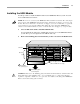
Installation 1-5 Installing the HSSI Module Cabling the HSSI Module for Network Connection A SCSI-type cable connects the HSSI Module DTE connector to a Data Service Unit (DSU). Table 1-1 describes the connectors. Table 1-2 describes the pin assignments. 3Com recommends using minimum lengths of this cable, especially if you plan to use these serial lines at high speeds. The maximum cable length allowed is 50 feet.
1-6 Installation Installing the HSSI Module CAUTION: Connections between 3Com equipment and other equipment and peripherals must be made using shielded cables in order to maintain compliance with FCC, and other agency radio frequency emissions limits. All interconnection cables should be equipped with shielded connectors. The backshells of these connectors must completely surround the cable shield.
Chapter 2 Troubleshooting and Maintenance This chapter describes how to troubleshoot and maintain the HSSI module. If you are unable to resolve a problem with your HSSI module, you will need to contact a customer service representative. Refer to Appendix C, “Technical Support,” for information about who to contact in your area. Troubleshooting Startup Problems The following symptom indicates a self-test failure at startup.
2-2 Troubleshooting and Maintenance Maintaining the HSSI Module Replacing the HSSI Module If any component in the HSSI module fails, you will need to replace the entire module. The HSSI module can be hot-swapped, which means that you can safely remove and install a new one without turning off or rebooting the NETBuilder base system. To perform the following procedure, you may need a small flathead screwdriver. To replace the module, follow these steps to remove the HSSI module: 1.
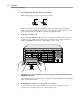
Appendix A HSSI Module Components This appendix describes the HSSI module components and gives the specifications of the board. The following figures show the major components and the connector/LED panel. Status LED CA LED TX LED Connector Backplane connector to NETBuilder II TX CA HSSI ® STATUS LEDs The following table explains the states of the three LEDs. Table A-1.
A-2 HSSI Module Components Connectors Connectors There are 4 connectors on the HSSI module. Table A-2. HSSI Module Connectors Location Connector Number of pins Purpose Backplane Connector: J1 and J3 48-pin connects module to the core bus J2 8-pin power connector 50-pin SCSI II 50-pin connects module to HSSI interface Front LED/connector panel: Specifications The following table lists the physical dimensions of the HSSI module. Table A-3.
Appendix B Displaying the MAC Address After you have installed the HSSI module, use this procedure to display the MAC address. This method of accessing the monitor can be done only from the bridge/router software. To find out about other methods of accessing the monitor utility, refer to the NETBuilder Family Bridge/Router Guide. NOTE: Using the MONitor command halts the normal operation of the bridge/router software. 1.
B-2 Displaying the MAC Address 5. When you are finished with the display of I/O module information, type G. This will exit the monitor mode and return you to the bridge/router software interface.
Appendix C Technical Support 3Com provides easy access to technical support information through a variety of services. This appendix describes these services. Automated Fax Service 3Com’s interactive fax service, 3ComFactsSM, provides technical information on 3Com products 24 hours a day, seven days a week. To access this service, dial 1-(408)-727-7021 from anywhere in the world using your touch tone telephone. In Europe, call (44) 442 278279.
C-2 Technical Support 3Com Documentation on CD-ROM Adapter-Specific Bulletin Board System (BBS) This private BBS, called CardBoardSM, contains patches and drivers for 3Com adapter products, as well as technical articles. To access CardBoard, call the CardBoard telephone number nearest to your location: France (33) (1) 69 86 69 54 Modem set up to 9600 baud, 8 data bits, no parity, 1 stop bit. Germany (49) 89 62732-188 or (49) 89 62732-189 Modem set up to 9600 baud, 8 data bits, no parity, 1 stop bit.
Technical Support C-3 Additional Technical Support Services contact your nearest 3Com sales office. To find the 3Com sales office nearest you, call 1-800-NET3Com (638-3266).
C-4 Technical Support Additional Technical Support Services ■ ■ Failure symptoms with diagnostic error messages, if applicable Proof of purchase for warranty repairs If you send a product to 3Com for repair without an RMA number displayed clearly on the outside of the box, it will be returned to you unopened. Paying for Repairs. You may pay for repairs by C.O.D., MasterCard®, or VISA®.
Technical Support C-5 Additional Technical Support Services ■ Factory repair service ■ Spare parts ■ Software update service You can receive information about these programs and services from your authorized 3Com network supplier or directly from 3Com by calling 1-800-NET-3Com or the 3Com sales office nearest you. Europe and Africa Authorized 3Com network suppliers often are equipped to provide repair service. Contact your network supplier first for assistance.
C-6 Technical Support Additional Technical Support Services ■ Make sure that the packing list you include with your equipment has the following information on it: – – – – – Reference number you assigned to the equipment (for equipment under warranty) Model, item, or part number Unit or board serial number (for warranty repairs only) Proof of purchase (for end customer warranty repairs) Fault diagnosis attached to each unit ■ Pack equipment carefully.