AT&T ® MERLIN Plus COMMUNICATIONS SYSTEM Release 2 Installation Manual
©1988 AT&T All Rights Reserved Printed in USA Issue 1 August, 1988 NOTICE The information in this document is subject to change without notice. AT&T assumes no responsibility for any errors that may appear in this document. MERLIN is a registered trademark of AT&T. IDEAL EZ Check is a registered trademark of Ideal Industries, Inc. To order copies of this document, call the AT&T Customer Information Center, 1-800-432-6600 and include the document number 518-600-008 with your order.
Contents 1 Introduction Step 1: Installing the Control Unit FCC Regulations Prepare the Network Interface Test the Outside Lines Mounting the Control Unit Insert the Modules Connect the Control Unit to the AC Outlet Connect the Outside Lines to the Control Unit Step 2: Wiring the Voice Terminals Preparation Considerations Voice Terminal Wiring Procedure Step 3: Connecting the Voice Terminals Prepare the Voice Terminals Connect Each Voice Terminal to the System Testing Each Voice Terminal Auxiliary Line
FCC Registration and Repair Information 53 Appendix A: System Connectivity Overview 55 Appendix B: Quick Reference Installation Requirements 57 Connecting the control unit Appendix C: Grounding Requirements Before You Turn the Power On External Grounding Appendix D: Wiring Reference Tables Typical System Wiring Installation Appendix E: Direct Connection Wiring Direct Connection Index 60 61 61 63 65 67 69 69 I-1
Introduction This manual shows you how to install and test a MERLIN®Plus Communications System, Release 2. You should perform the tasks in the order presented since many of the early tasks prepare the system for those to be performed later. The following is a brief overview of the installation steps in this manual: ● Set up and connect the system’s control unit, beginning with the network interface, as described in "Step 1: Installing the Control Unit.
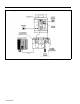
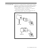
Figure 1 A typical MERLIN Plus system overview.
Step 1: Installing the Control Unit FCC REGULATIONS To comply with FCC regulations, notify your local telephone company of the following before permanently connecting your system to their lines: ● System registration number: AS593M-13529-KF-E ● Ringer equivalence number: 0.8A ● Telephone numbers of the lines to which you are connecting your system For more information on FCC requirements and regulations, see "FCC Registration and Repair Information" at the end of this manual.
The 2-line adapter has two jacks, each of which carries a single-pair line from the 2-line network interface jack. The 50-pin connector (attached to a 66-type block) carries up to 25 lines. You can connect your outside telephone lines from these (or other) network interface connectors to the control unit in many ways. The method you use to connect your outside telephone lines to the control unit depends on the type of network interface the local telephone company installs at the control unit location.
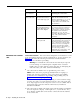
TEST THE OUTSIDE LINES You may want to test whether a dial tone is audible at the network interface connection. If so, you need either a basic rotary dial telephone, a Touch-Tone telephone with a modular cord, or a tool that tests for dial tones. Because a MERLIN Plus system voice terminal works only with a control unit, you cannot use a MERLIN Plus system voice terminal for this test.
If And Go on to the next procedure, "Mounting the Control Unit." Each outside line has a dial tone A line does not have a dial tone MOUNTING THE CONTROL UNIT Do This The jack for that line at the network interface is a 1-line (RJ11-type) jack Have the local telephone company check the line and the network interface. Meanwhile, go on to the next procedure, "Mounting the Control Unit," and continue with the installation.
● The control unit is within 6 inches of a jack field. ● The network interface is available for installation or has already been installed. ● The wiring runs from the control unit to the voice terminal locations do not exceed 1000 feet. ● The temperature range of the location is between 40 and 104 °F (4 to 40 °C). ● The control unit location is safe from sources of extreme heat (furnaces, heaters, attics, or direct sunlight).
Equipment Four 1 1/4-inch No. 8 self-tapping screws come with the system for mounting the unit on a wall. Regardless of the mounting surface, you will need a long-shafted screwdriver for your installation. However, the construction of the wall you have selected for mounting the control unit determines if you will need additional or substituted items for mounting. You will need: If the mounting surface is: Concrete Brick Concrete block Four 1 1/4-inch No.
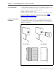
Locate the back of the control unit and note the four screw holes used for securing the control unit to the wall (Figure 6). FIGURE 6 The control unit (rear view). As noted in Figure 6, the horizontal distance between the center of these holes measures 8 3/8 inches, and the vertical distance measures 14 7/16 inches. Make note of these measurements since you may need them to locate and drill mounting holes in the wall.
Remove the top cover by first unscrewing the screw located at the center bottom of the cover. This screw is designed to stay in the hole of the cover after it has been removed from the control unit. Press down on the tab located at the center of the top and back edge and pull the top cover away, as shown in Figure 8. Once these covers are removed, you can reach the screw holes from the front of the unit. FIGURE 8 The top cover removed, revealing top screw holes.
FIGURE 9 Mounting the control unit on the wall.
INSERT THE MODULES The control unit comes with covers in place and with the following modules already installed: ● Power supply module ● Memory module ● Line module (line board) ● Voice terminal module (station board) You have already removed the front and top covers to mount the unit on the wall. The power supply module is on the left inside the control unit. See Figure 10. The memory module houses a battery that will preserve all programming for at least four days in case of a power failure.
Inserting a Line Module Make sure that the power switch is off and that the system is unplugged from the power source. Then do as follows: 1 Be sure the top and front covers are off. 2 Locate the slot immediately to the right of the line module already installed. Notice the plastic channels at the top and bottom of the slots. 3 Align the top and bottom edges of the line module to the channel openings so that the gold connectors face in and the components face out and to the right of the slot.
Inserting a Voice Terminal Module Make sure the power is off, the control unit is not plugged into the power source, and the covers are off. Then locate the slot between the voice terminal module and the line module already in place. Align the edges and install the voice terminal module using the same procedure you used for inserting the line module. Check to see that the module is securely in place. See Figure 12 at (a).
CONNECT THE CONTROL UNIT TO THE AC OUTLET The ac outlet should be a 117-volt, 60-Hz, 3-prong, third-wire grounded outlet. You should have an electrician check the outlet’s third wire to make sure the outlet is properly grounded. Proper grounding helps protect the system against damage from power surges caused by static discharges and lightning. See "Appendix C: Grounding Requirements" before connecting the control unit to the power source.
If Then The green power light doesn’t go on and the orange light on the power switch also doesn’t go on Test the outlet by plugging in a radio or a lamp. The green power light is on, but the orange power switch light is off . The outlet is not functioning, is miswired or improperly grounded. Have it repaired or use another outlet. The green power light is off but the orange power switch light is on and the outlet is working properly Stop the installation.
FIGURE 14 A System Configuration Form. See Figure 15 and follow this procedure to connect your outside lines: 1 Refer to your System Configuration Form when connecting the outside lines you’ve assigned to each line jack on the control unit. The outside line numbers are the telephone numbers listed at the network interface. 2 Mark or label a D2R cord on both ends with "A." 3 Plug one end of the line cord into the control unit jack labeled "A.
FIGURE 15 The control unit connected to labeled outside lines. NOTE: If you’re in an area with frequent lightning activity or severe transient voltage and are using the 147A Protector (see CIB 3109), the outside lines from the control unit plug into corresponding jacks on the protector itself.
Step 2: Wiring the Voice Terminals PREPARATION CONSIDERATIONS Before connecting the voice terminals to the control unit, keep your System Configuration Form handy and review the following: Locations ● The wiring run from the control unit to a voice terminal location cannot exceed 1000 feet. ● A voice terminal located in another building requires two Model 341 InRange, Out-of-Building (IROB) protectors. (See Section 5, "Reference," in the System Manual for more information on IROB protectors.
Intercom 19 and Printed Reports ● Printed reports require a MERLIN Plus System Data Collector and a printer (AT&T 475 or equivalent). ● The MERLIN Plus system is capable of printing for your use two kinds of reports. The Call Report (also known as the Station Message Detail Recording [SMDR]) prints records of outgoing and/or incoming calls.
VOICE TERMINAL WIRING PROCEDURE When you planned your system, you recorded the intercom numbers for specific locations within your business on the System Configuration Form. Check and make a note of these assignments now, before you begin connecting the voice terminals to the control unit. When you are ready, install the voice terminal wiring as follows: 1 Use your System Configuration Form as a reference for each intercom number. 2 Mark or label a D8W cord on one end with "10.
Step 3: Connecting the Voice Terminals Any of the following voice terminal models will work at any voice terminal location connected to your MERLIN Plus system: ● 5-Button voice terminal ● BIS-10 voice terminal ● 10-Button voice terminal ● 10-Button voice terminal with Hands Free Answer on Intercom (HFAI-10) ● BIS-22 voice terminal ● BIS-34D with Display voice terminal ● BIS-34 voice terminal ● 34-Button (SP-34) voice terminal with speakerphone ● 34-Button (SP-34) voice terminal with speake
NOTE: The control unit power should be off at this point. However, if the power is on and the other end of this modular voice terminal cord is already plugged into the control unit, a red light may go on next to a button when you plug the cord into the line jack on the voice terminal, and the voice terminal may ring. Don’t be alarmed. The red light should go on if the control unit power is on; go to the next step.
CONNECT EACH VOICE TERMINAL TO THE SYSTEM Since the voice terminal module can be damaged if a modular cord is unplugged while there is power to the control unit, make sure that the control unit power is off before connecting each voice terminal to the system. This prevents you from damaging the voice terminal module if you accidentally pull on a cord that is attached to it.
FIGURE 19 Adjusting the Speakerphone volume. FIGURE 20 Verifying correct tone and light operation.
If the lights do not flash: 1 Check the green power light on the control unit. 2 Check the wiring run from the control unit to the voice terminal. Then If Do This The green power light is on Go on to Step 2. The green power light is off Make sure the power cord is plugged into the ac outlet. Then set the power switch on the control unit to Off and back again to On. If the green power light still does not go on, contact your equipment supplier for assistance before continuing with the installation.
Verify Intercom Number Verify the voice terminal’s intercom number as follows: 1 Touch the fifth button down (Intercom) in the leftmost row of buttons. See Figure 21. 2 Touch Speakerphone or lift the handset. 3 Dial the voice terminal’s intercom number. A busy signal verifies the intercom number. Identify Each Voice Terminal As you test the voice terminals, label each one with its intercom number as follows: 1 Fill in an intercom number label for each voice terminal.
FIGURE 21 Verifying and labeling the intercom number.
AUXILIARY LINE TELEPHONE The auxiliary jack (the top jack) on each line module bridges and monitors the outside line connected to the first line jack (the second jack from the top, line A) on the module. If you have a second line module, its auxiliary jack connects to line E, and you can gain access to it with a basic Touch-Tone or rotary dial telephone. Note the location of the Aux jack in Figure 22. This jack provides many services.
Step 4: Testing the System Now that your system is in place, you should test it to make sure that it’s operating properly. The following tests will help you determine if your system’s components are working as they should. If these tests reveal any problems, find their solution in Section 7, "Troubleshooting the System," in the System Manual and take the recommended corrective action. CAUTION: Turn the control unit power off when plugging and unplugging modular cords.
FIGURE 23 Plugging in a voice terminal to test jacks for dial tone. FIGURE 24 Testing voice terminal jacks for dial tone.
PLACE AN OUTSIDE CALL To make sure you can use your system to place an outside call, use any voice terminal in your system and do as follows: 1 Touch Speakerphone or lift the handset. The green light goes on next to the red light. 2 Dial an outside number where you know someone will answer the call. 3 After the call is answered, ask the person who answers to hold, and place the call on hold by touching Hold. See Figure 25. The green light next to the line button flashes rapidly.
PLACE AN INTERCOM CALL To make sure you can use your system to place an intercom call, perform this test from one voice terminal to another in your system. Make sure someone is available to answer the intercom call. See Figure 26. 1 At any voice terminal in your system, touch the fifth button down (Intercom) in the leftmost row of buttons. The red light next to the button goes on. 2 Touch Speakerphone or lift the handset. The green light next to the red light goes on, and you hear a dial tone.
3 Dial the intercom number for the voice terminal where the other person is waiting for the call. Through the speaker or your handset you’ll hear the other voice terminal ring. At the other voice terminal, one long beep sounds, the red light glows steadily next to the fifth button down (Intercom) in the leftmost row of buttons, and the green light next to the red light flashes. 4 When the other person answers, speak into your speaker or handset to verify two-way communication.
Step 5: Adding Accessories Once you have installed your MERLIN Plus system, you may want to add accessories to enhance its capabilities. ACCESSORY EQUIPMENT You can connect the headset adapter or the general purpose adapter to the port labeled OTHER on the voice terminal.
You can also add accessory equipment to the system that plugs into the control unit. You can add a data collector and printer to your system to collect data on calls and print Call Reports. The 450F adapter allows the data collector to share port 19 with the Busy Buster feature. Refer to the MERLIN Plus System Manual for more information on Busy Buster. See Figure 28.
FIGURE 29 MERLIN Plus system Basic Telephone Modem Interface. If you have a compatible audio system, you can connect it to the Music-onHold jack to provide background music or prerecorded messages for incoming calls. See Figure 30. Caution Users of equipment that rebroadcasts copyrighted music or other material may be required to obtain a copyright license from a third party, such as ASCAP or BMI.
FIGURE 30 MERLIN Plus system Music-on-Hold jack. FIGURE 31 MERLIN Plus system Loudspeaker Page connected to CO line.
FIGURE 32 MERLIN Plus system alerters. FIGURE 33 MERLIN Plus system CO line wiring accessories. Supplemental alert adapters allow you to connect alerting devices such as horns, bells, and strobe lights to your system. See Figure 32. See Figure 33 for other Central Office (CO) line accessories and voice terminal wiring accessories. To add accessory equipment to your system, follow the instructions that come with the components.
Accessories that Extend Telephone Range You may have to provide a voice terminal power supply for a voice terminal located more than 1000 feet from the control unit. In such cases, you’ll need a power supply kit that allows you to double the range of the wiring run from the control unit to the voice terminal. See Figure 34.
FIGURE 35 An ln-Range, Out-of-Building protector.
Step 6: Changing the System Your MERLIN Plus communications system is designed so that you can make changes quickly and easily. You can increase your system’s capacity by adding outside lines or voice terminals. Modular plugs on much of the system wiring and labels on key components make it easy for you to reorganize the system in the event of office rearrangement. The most common system changes are adding an outside line, adding a voice terminal, and moving a voice terminal.
MOVING A VOICE TERMINAL You can easily move a voice terminal from one location to another within your system without having to reprogram the voice terminal. To move a voice terminal, see Figure 36 and do as follows: 1 Make sure the necessary wiring is in place or is available. (See "Step 2: Wiring the Voice Terminals".) 2 Unplug the voice terminal at its old location, and plug it in at its new location. 3 At the jack field, locate the cord labeled with the voice terminal’s intercom number.
Jack Field Wiring Supplement A jack field is a group of jacks at the control unit location that serves as a point of administration for telephone wiring. This section tells you how to construct a jack field and how to extend the network interface provided by the local telephone company to the jack field.
CONSTRUCTING AND CONNECTING THE JACK FIELD While you can connect your voice terminal locations to your control unit in any of several different ways, the method described here greatly simplifies certain aspects of system administration. This method calls for wiring runs that terminate in modular wall jacks at the voice terminal locations and in modular jacks in a jack field at the control unit location.
● Use spooled DIW cable. ● Use labels. You probably need most, if not all, of the following tools and equipment to complete your wiring installation. Which items you need depends mostly on the layout, dimensions, and structural particulars of your place of business. ● Cable stripping tool You need a tool for stripping the outside jacket from the cable without damaging the wires.
Constructing a Jack Field The control unit must be placed within 5 feet of an ac outlet, within one cord length (7, 14, 25 feet or up to a 400 feet of spooled DIW cable) of the network interface, and 6 inches above a jack field. See Figure 38. FIGURE 38 A well-positioned control unit. At the location where you plan to install your control unit, do as follows: 1 Use the measurements in Figure 38 to mark positions on a wall (or other mounting surface) for the control unit and the jack field.
5 Snap as many Z601A adapters as you need into the boxes, filling the boxes from top to bottom. — If one of the jacks on the adapter has a black dot on it, make sure that the jack with the black dot faces to the right. — If you are using cutdown-to-modjack adapters, make sure the jacks on the adapters face to the right. FIGURE 39 Attaching jack boxes to create a jack field. Running the Cables Follow these steps to run cables from the jack field to your voice terminal locations (Figure 40).
FIGURE 40 Running the cables. Terminating the Wiring Runs in Modular Wall Jacks There are many types of wall jacks used to terminate wiring runs. The type of wiring (concealed, surface mount, wall-mounted telephone, group office, and so forth) determines the type of wall jack to be used.
EXTENDING THE NETWORK INTERFACE TO THE JACK FIELD If the local telephone company has provided an RJ21-type network interface, you cannot connect your control unit to the network interface directly with modular line cords. You must first extend the network interface to a group of single-pair modular jacks mounted in a jack panel box in the jack field. Then connect the control unit to your outside lines by plugging the modular line cords into the jacks.
Add Jacks to the Jack Field To add jack boxes to the jack field, do the following: 1 Position the jack panel box so that the door with the handle is on the right (as you face it), and attach it to the top box in the rightmost column of boxes already in the jack field by meshing the tongues and grooves. 2 Use appropriate screws to attach the jack panel box to the mounting surface that supports the jack field. 3 Pull the two plastic caps off the connecting block on the 4-line adapter, and set the caps aside.
5 Attach the telephone number directory to the inside of the jack panel box’s left door, then close it. You should now have a single-pair modular jack in the jack field for each outside line.
FCC Registration and Repair Information This equipment is registered with the FCC in accordance with part 68 of its Rules. In compliance with the Rules, you are advised of the following: Means of Connection You must connect this equipment to the telephone network through several standard network interface jacks, USOC RJ11C or RJ14C, or a multiline network interface cable and a USOC RJ21 connector. You can order these from your local phone company.
Appendix A: System Connectivity Overview Figure 42 illustrates system connectivity. FIGURE 42 Typical MERLIN Plus system connectivity.
Appendix B: Quick Reference Installation Requirements Before you install the control unit, make sure that the installation area meets the following requirements. Environment The environment for the control unit should be as follows: ● Temperature: 40 to 104 °F (4 to 40 °C). ● Humidity: not to exceed 80%. ● Airborne Contamination: no exposure to corrosive gases, dust, chemicals, or similar substances. ● Ventilation: 1-inch space above and to the sides.
AC Outlet Check Check, or have checked by a qualified electrician, the outlet into which your MERLIN Plus system control unit will be plugged. Check that the hot, neutral, and ground wires are properly connected to the outlet by using an IDEAL EZ Check®circuit tester (IDEAL Industries, Inc., model 61035) or equivalent circuit tester. The outlet can also be tested using a voltmeter by taking the measurements shown in Figure 43. FIGURE 43 Proper ac outlet measurements.
FIGURE 44 Mounting the control unit on the wall.
CONNECTING THE CONTROL UNIT Before connecting the control unit to the system, see Figure 45 and be sure of the following: ● The building wiring is completely installed. ● The jack field labels correspond with the distant end locations. ● The distant end labels correspond with the jack field labels (optional). ● The network interface labels have the correct telephone numbers. FIGURE 45 Connecting the control unit. Make sure the control unit power is off before connecting system wires.
Appendix C: Grounding Requirements Proper grounding is fundamental for the MERLIN Plus Communications System for protection against: BEFORE YOU TURN THE POWER ON ● Lightning ● Power surges ● Power crosses on Central Office (CO) lines ● Static discharge Check the following considerations before you turn the power on for the MERLIN Plus system. Grounding Requirements The control unit, the CO line protector, and the ac power service panel should be as close to each other as possible.
3 Visually verify that individual CO line protectors (carbon blocks, gas tubes, etc) are in place. 4 Set the VOM to the scale on which you can read 1 VAC. 5 Measure voltage between CO protector ground lug and the third wire ground of the nearest ac outlet on the circuit to be used. This voltage should be less than 1 VAC. WARNING: If the ac voltage reading is greater than 1 volt, do not measure resistance in the following step as this measurement could damage the VOM.
EXTERNAL GROUNDING If the CO line protector is properly grounded and bonded to ac power, most lightning damage will be prevented. NOTE: In areas of the country with frequent lightning activity or severe ac transient voltage, additional protection is strongly recommended. Either of the following methods are acceptable: ● Install an AT&T model 147A Protector for ac and CO lines. The 147A Protector has a capacity of four CO lines.
FIGURE 46 Typical MERLIN Plus system grounding plan.
Appendix D: Wiring Reference Tables TABLE D-1 Wiring Parts Cross Reference. PPEC Description 61400 2750-D14 2750-D08 2750-D07 Net Intf Adptr Net Brdg Adptr 61407 NI/CU Mod Cord CU Jumper Cord Cbl Strp Tool 1000 ft 4-Pr Cable 61208 32910 Apparatus Code COMCODE SKU Z122C Apparatus Box 2A Adapter Mounting Z601A Adapter Z610A Adapter 267C Adapter 267A2 Adapter 103A Corm Block 102A Corm Block 65B Faceplate D2R-29 Cord 7 ft D8W-87 Cord 2.
TABLE D-3 CO Line Wiring, 6-Position Jack, Single-Pair. RJ11 NI Specification D2R Cord CU Line Jack Signal T Pin 4 Plug Plug 3 4 Pin Signal T 3 R 3 Color GREEN R 4 4 3 RED TABLE D-4 CO Line Wiring, 6-Position Jack, Two-Pair. Signal T1 R1 P i n Color GREEN 4 RED 3 2 5 T2 R2 BLACK YELLOW 267C Adapter 267A2 Adapter RJ14 NI Specification Plug 4 3 Jack 1 4 3 Jack 2 4 3 Plug 4 3 2 5 2 5 2 5 2 5 Jack Pin 1 4 3 2 4 3 TABLE D-5 CO Line Wiring, 6-Position Jack, Multipair.
TYPICAL SYSTEM WIRING INSTALLATION Figure 47 shows a typical wiring installation for a MERLIN Plus system. Local telephone lines connect with system wiring at a network interface. Voice terminal wiring connects to the control unit through building wiring and a jack field. FIGURE 47 Typical MERLIN Plus system wiring installation.
TABLE D-6 Material List for 8 Telephones and 3 Lines (Figure 47). Voice Terminal Wiring Item Qty 102A Connecting Block (1 shown) 65B Faceplate (1 shown) 103A Connecting Block (1 shown) 1000 ft Cable Spool, DIW Z122C Apparatus Box Z601A Adapters D8W Cords, 2.
Appendix E: Direct Connection Wiring You can connect your voice terminal locations in either of two ways: ● Through the building wiring to a jack field at the control unit location. or ● Directly, with modular voice terminal cords and, if necessary, modular voice terminal extension cords. Jack field wiring is the recommended method for almost all cases. This method is illustrated and explained throughout this manual. However, if you need to use direct connection wiring, use the following instructions.
FIGURE 48 Voice terminal wiring, direct connection.
Any of the following voice terminal models will work at any voice terminal location directly connected to your MERLIN Plus system: ● 5-Button voice terminal ● BIS-10 voice terminal ● 10-Button voice terminal ● 10-Button voice terminal with Hands Free Answer on Intercom (HFAI) ● BIS-22 voice terminal ● BIS-34 voice terminal ● BIS-34D voice terminal ● 34-Button (SP-34) voice terminal with speakerphone ● 34-Button (SP-34) voice terminal with speakerphone and display ● 34-Button deluxe voice
5 Plug the cord for the new location into the corresponding control unit jack with the voice terminal’s intercom number. 6 Relabel the cord at the new location and again at the control unit end. 7 Turn the control unit back on. 8 Record the change. You do not have to reprogram the voice terminal.
Index A Accessories, 29 adding, 35 – 41 Accessory equipment, 35 Adapter, 4-line, 50, 51 RJ11-type, 3, 4 RJ14-type, 3, 4 Z601A, 45, 48 Adding a voice terminal. See Voice terminal, adding Apparatus box, 50, 60 Auxiliary jack, 16, 29 Auxiliary line, 16 Auxiliary line telephone, line module jack, 29 B Battery, 12 BIS voice terminals.
M Memory module, 12 Modules, inserting, 12 – 14 Moving a voice terminal.
518-600-008