
User Guide Hub/Switch SuperStack II Switch 1000

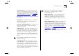
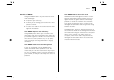
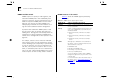
Table Of Contents
- About This Guide
- Getting Started
- Installation and Setup
- Setting Up for Management
- Managing The Switch 1000
- Setting Up Users
- Creating a New User
- Deleting a User
- Editing User Details
- Assigning Local Security
- Choosing a Switch Management Level
- Setting Up the Switch Unit
- Setting Up the Switch Ports
- Setting Up the Switch Database (SDB)
- Setting Up Resilient Links
- Setting Up Traps
- Setting Up the Console Port
- Resetting the Switch
- Initializing the Switch
- Upgrading Software
- Advanced Management
- Status Monitoring and Statistics
- Safety Information
- Screen Access Rights
- Trouble-shooting
- Pin-outs
- Switch 1000 Technical Specifications
- Technical Support
- Glossary
- Index
- 3Com Corporation Limited Warranty
- Electro-Magnetic Compatibility

5-18 C
HAPTER
5: A
DVANCED
M
ANAGEMENT
Configuring STP on the Switch
CAUTION: You should not configure any STP
parameters unless you have considerable knowl-
edge and experience with STP.
Configuring the STP Parameters of VLANs
The Switch has a completely separate STP system for
each VLAN that you have specified. Each VLAN has
its own Root Bridge, Root Ports and BPDUs.
The VLAN STP screen allows you to set up and
manage an STP system for each VLAN on the
Switch. To access the VLAN STP screen:
1
From the Main Menu, select SWITCH MANAGE-
MENT. The Switch Management screen is displayed.
2
In the Management Level field, choose VLAN.
3
Choose the STP button. The VLAN STP screen is dis-
played, as shown in Figure 5-16
.
The VLAN STP screen shows the following:
VLAN ID
1 / 2 / 3 / ... 15
This field allows you to
specify the VLAN to be configured.
If you are using STP, you cannot use VLAN 16. Also,
if you are using AutoSelect VLAN Mode, you cannot
use VLAN 15. In these cases, the relevant VLANs are
used internally by the Switch and are therefore not
available.
Topology Changes
This read-only field shows the
number of network topology changes that have
occurred in the current VLAN.
Figure 5-16
VLAN STP screen
Max Age
6...40
This read-only field shows the
time (in seconds) that the Switch waits before trying
to re-configure the network. If the Switch has not
received a BPDU within the time specified in this
field, it will try to re-configure the network topol-
ogy.
Designated Root
This read-only field shows the
Bridge Identifier of the designated Root Bridge.
Hello Time
1...10
This read-only field shows the
time delay, in seconds, between the transmission of
BPDUs from the Switch.
Root Cost
This read-only field shows the path cost
from the Switch to the Root Bridge.