
User Guide Hub/Switch SuperStack II Switch 1000
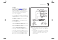
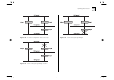
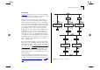
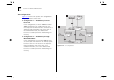
Table Of Contents
- About This Guide
- Getting Started
- Installation and Setup
- Setting Up for Management
- Managing The Switch 1000
- Setting Up Users
- Creating a New User
- Deleting a User
- Editing User Details
- Assigning Local Security
- Choosing a Switch Management Level
- Setting Up the Switch Unit
- Setting Up the Switch Ports
- Setting Up the Switch Database (SDB)
- Setting Up Resilient Links
- Setting Up Traps
- Setting Up the Console Port
- Resetting the Switch
- Initializing the Switch
- Upgrading Software
- Advanced Management
- Status Monitoring and Statistics
- Safety Information
- Screen Access Rights
- Trouble-shooting
- Pin-outs
- Switch 1000 Technical Specifications
- Technical Support
- Glossary
- Index
- 3Com Corporation Limited Warranty
- Electro-Magnetic Compatibility

5-16 C
HAPTER
5: A
DVANCED
M
ANAGEMENT
STP Configurations
Figure 5-14 shows two possible STP configurations
using SuperStack II Switch units:
■
Configuration 1 — Redundancy for Back-
bone Link
In this configuration, a Switch 1000 and Switch
3000 TX both have STP enabled and are con-
nected by two Fast Ethernet links. STP discovers a
duplicate path and disables one of the links. If
the enabled link breaks, the disabled link
becomes re-enabled, therefore maintaining con-
nectivity.
■
Configuration 2 — Redundancy through
Meshed Backbone
In this configuration, four Switch 3000 TX units
are connected such that there are multiple paths
between each one. STP discovers the duplicate
paths and disables two of the links. If an
enabled link breaks, one of the disabled links
becomes re-enabled, therefore maintaining con-
nectivity.
Figure 5-14
STP configurations