® SuperStack® II Switch 1000 User Guide Agent Software Version 3.1 http://www.3com.com/ Document No.
3Com Corporation ■ 5400 Bayfront Plaza Copyright © 3Com Ireland, 1997. All rights reserved. No part of this documentation may be reproduced in any form or by any means or used to make any derivative work (such as translation, transformation, or adaptation) without permission from 3Com Ireland. 3Com Ireland reserves the right to revise this documentation and to make changes in content from time to time without obligation on the part of 3Com Ireland to provide notification of such revision or change.
CONTENTS Switch 1000 on Your Network 1-6 Server Connections 1-6 Network Configuration Examples 1-6 Network Segmentation I 1-7 Network Segmentation II 1-8 Desktop Switching 1-9 Unit Overview — Front 1-10 10BASE-T Ports 1-11 100BASE-TX Port 1-11 LEDs 1-11 Unit Overview — Rear 1-12 Power Socket 1-13 Unit Serial Number 1-13 Redundant Power System Socket 1-13 Reset Button 1-13 Console Port 1-13 Plug-in Module Slot 1-13 Transceiver Module Slot 1-13 Ethernet Address 1-13 Unit Defaults 1-14 Managing the Switch 100
Configuration Rules for Fast Ethernet 2-2 Configuration Rules with Full Duplex 2-2 Installing the Switch 1000 2-4 Rack Mounting 2-4 Stacking the Switch and Other Units 2-4 Wall Mounting 2-5 Powering-up the Switch 2-6 Connecting a Redundant Power System (RPS) 2-6 Connecting Equipment to the Console Port 2-7 Connecting a VT100 Terminal 2-7 Connecting a VT100 Terminal Emulator 2-7 Connecting a Workstation Running SLIP 2-8 3 4 Setting Up Users 4-2 Creating a New User 4-3 Deleting a User 4-4 Editing User Deta
How VLANs Ease Change and Movement 5-2 How VLANs Control Broadcast Traffic 5-2 How VLANs Provide Extra Security 5-2 An Example 5-2 VLANs and the Switch 5-3 The Default VLAN and Moving Ports From the Default VLAN 5-3 Connecting VLANs to a Router 5-3 Connecting Common VLANs Between Switch Units 5-3 Using AutoSelect VLAN Mode 5-3 Using Non-routable Protocols 5-5 Using Unique MAC Addresses 5-5 Extending VLANs into an ATM Network 5-5 VLAN Configurations 5-5 Example 1 5-5 Example 2 5-6 Example 3 5-7 Setting Up VL
Fault Log 6-9 Remote Polling 6-10 A SAFETY INFORMATION Important Safety Information A-1 Power Supply and Fuse A-3 Sockets for Redundant Power System (RPS) A-3 RJ45 Ports A-3 Fiber Ports A-3 L’information de Sécurité Importante A-4 La Source de Courant et Le Fusible A-5 Socle Pour Alimentation Multiple A-5 Les Ports RJ45 A-6 Les Ports Fibre A-6 Wichtige Sicherheitsinformationen A-7 Stromversorgung und Sicherung A-8 Steckdose für Redundant Power System (RPS) A-8 RJ45 Anschlußen A-8 Glasfaser Anschlußen A-8
ABOUT THIS GUIDE About This Guide provides an overview of this guide, describes the guide conventions, tells you where to look for specific information and lists other publications that may be useful. Introduction This guide provides the information you need to install and configure the SuperStack® II Switch 1000 24 Port (3C16900A) and the SuperStack II Switch 1000 12 Port (3C16901A) with v3.1 agent software.
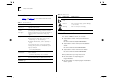
2 ABOUT THIS GUIDE Table 2 Conventions Notice Icons Icon Table 1 and Table 2 list conventions that are used throughout this guide. Table 1 Text Conventions Convention Description Screen displays This typeface represents information as it appears on the screen. The words “enter” and “type” When you see the word “enter” in this guide, you must type something, and then press the Return or Enter key. Do not press the Return or Enter key when an instruction simply says “type.
1 GETTING STARTED ■ Full duplex on all fixed Ethernet and Fast Ethernet ports, and Fast Ethernet Plug-in Module ports ■ Security ■ Resilient Links ■ Support for 16 Virtual LANs (VLANs) ■ Spanning Tree Protocol (STP) per VLAN ■ PACE (Priority Access Control Enabled) for supporting multimedia applications over Ethernet ■ 3Com’s SuperStack II architecture: About the Switch 1000 Part of 3Com’s SuperStack® II range of products, the Switch 1000 is designed to overcome the common problem of insuffic
1-2 CHAPTER 1: GETTING STARTED Port Connections 10BASE-T Ports The Switch has 12 or 24 10BASE-T ports configured as MDIX (cross-over), which provide a full 10Mbps bandwidth to attached endstations. Maximum segment length is 100m (328ft) over grade 3, 4, or 5 twisted pair cable. As these ports are configured as MDIX (cross-over), you need to use a cross-over cable to connect to devices whose ports are MDIX-only. Most of the 10BASE-T ports in 3Com devices are MDIX-only.
About the Switch 1000 Switch Operation and Features Forwarding of Packets How Does the Switch Compare to a Bridge? The table below shows how Switch 1000 operation compares to that of a conventional IEEE 802.1d bridge. Address Learning Forwarding Mode IEEE 802.1d Bridge Switch 1000 All ports All ports except backbone port Store and forward Discard packets Operation when packet buffers full 1-3 The table below shows how a packet is processed when it arrives at the Switch 1000.
1-4 CHAPTER 1: GETTING STARTED To best suit your networking requirements, the Switch 1000 allows you to select one of four frame forwarding modes: ■ ■ ■ ■ Fast Forward — Frames are forwarded as soon as the destination address is received and verified. The forwarding delay, or latency, for all frames in this mode is just 40µs, but with the lack of checking time any error frames received are propagated through the switch.
About the Switch 1000 For more information about enabling full duplex, refer to “Setting Up the Switch Unit” and “Setting Up the Switch Ports” in Chapter 4. Security The Switch 1000 contains advanced security features which guard against users connecting unauthorized endstations to your network. When security is enabled on a port, it enters single address learning mode.
1-6 CHAPTER 1: GETTING STARTED ■ Redundant paths are enabled if the main traffic paths fail. For more information about STP, refer to “Spanning Tree Protocol” on page 5-12. PACE The Switch 1000 supports PACE (Priority Access Control Enabled) technology, which allows multimedia traffic to be carried over standard Ethernet and Fast Ethernet LANs.
Switch 1000 on Your Network Network Segmentation I This example shows how the Switch 1000 fits into a large corporate network with a Fast Ethernet infrastructure. A Switch is positioned on each floor and servers are centralized in the basement.
1-8 CHAPTER 1: GETTING STARTED Network Segmentation II This example shows the Switch 1000 in a second workgroup situation. This setup could be that of a small office within a large corporation, or part of a larger corporate network. Most of the switch ports have multiple endstations.
Switch 1000 on Your Network Desktop Switching This example shows Switch 1000 used for a group of heavy-traffic users in a large corporate network. Here switching is brought to the desktop with a single endstation per switch port. A local server is connected using the 100Mbps Fast Ethernet link.
1-10 CHAPTER 1: GETTING STARTED Unit Overview — Front Figure 1-4 Switch 1000 front view: 3C16901A top, 3C16900A bottom
Unit Overview — Front 10BASE-T Ports The Switch has 12 or 24 10BASE-T RJ45 ports configured as MDIX (cross-over), which provide a full 10Mbps bandwidth to attached endstations. The maximum segment length is 100m (328ft) over category 3, 4, or 5 UTP cable. As these ports are configured as MDIX (cross-over), you need to use a cross-over cable to connect to devices whose ports are MDIX-only. Most of the 10BASE-T ports in 3Com devices are MDIX-only.
1-12 CHAPTER 1: GETTING STARTED Unit Overview — Rear Figure 1-5 Switch 1000 rear view
Unit Overview — Rear Power Socket The Switch 1000 automatically adjusts to the supply voltage. The fuse is suitable for both 110V A.C. and 220–240V A.C. operation. For information on replacing fuses, refer to Appendix A. Unit Serial Number You may need this serial number for fault reporting purposes. Redundant Power System Socket Use one of these sockets to connect a SuperStack II Redundant Power System (RPS) to the unit. You can use either socket.
1-14 CHAPTER 1: GETTING STARTED Unit Defaults Managing the Switch 1000 The following table shows the factory defaults for the Switch 1000 features.
Quick Start For SNMP Users 1-15 3 At the Main Banner screen, press [Return] to dis- Quick Start For SNMP Users This section describes how to get started if you want to use an SNMP Network Manager to manage the Switch. It assumes you are already familiar with SNMP management. ■ ■ ■ If you are using IP and you have a BOOTP server set up correctly on your network, the IP address for the Switch is detected automatically and you can start managing the Switch without any further configuration.
1-16 CHAPTER 1: GETTING STARTED
2 INSTALLATION AND SETUP ■ Following Safety Information Before installing or removing any components from the Switch, or carrying out any maintenance procedures, you must read the safety information provided in Appendix A of this guide. ■ ■ When deciding where to position the unit, ensure that: ■ You are able to meet the configuration rules detailed in the following section. ■ The unit is accessible and cables can be connected easily.
2-2 CHAPTER 2: INSTALLATION AND SETUP Configuration Rules for Fast Ethernet The topology rules for 100Mbps Fast Ethernet are slightly different to those for 10Mbps Ethernet. Figure 2-1 illustrates the key topology rules and provides examples of how they allow for large-scale Fast Ethernet networks. The key topology rules are: ■ Maximum UTP cable length is 100m (328ft) over category 5 cable.
Configuration Rules with Full Duplex Figure 2-1 Fast Ethernet configuration rules 2-3
2-4 CHAPTER 2: INSTALLATION AND SETUP 3 Insert the three screws and fully tighten with a suit- Installing the Switch 1000 Rack Mounting The Switch is 1.5U high and fits in most standard 19-inch racks. CAUTION: Disconnect all cables from the Switch before continuing. Remove all self adhesive pads from the underside of the unit, if fitted. 1 Place the unit the right way up on a hard flat sur- face, with the front facing towards you.
Installing the Switch 1000 Wall Mounting A single Switch can be wall-mounted. CAUTION: Disconnect any cables from the unit before continuing. Remove self-adhesive pads from the underside of the unit if they have been previously fitted. 1 Place the Switch the right way up on a hard flat sur- face, with the front facing towards you. 2 Locate a mounting bracket over the mounting holes on one side of the unit, as shown in Figure 2-3. 3 Insert the two screws and tighten with a suitable screwdriver.
2-6 CHAPTER 2: INSTALLATION AND SETUP Powering-up the Switch 1 Connect the power cord to the IEC socket on the rear of the Switch, and to your mains socket. The Switch has no ON/OFF switch; the only method of connecting or disconnecting mains power is through the power cord. 2 The Switch enters a Power On Self Test (POST). The time taken for the test to complete is dependent on the type of POST configured (refer to “Switch Management Setup” on page 3-9 for details of how to configure the type of POST).
Connecting Equipment to the Console Port Connecting Equipment to the Console Port The Switch console port settings are set to: ■ 8 data bits ■ no parity ■ 1 stop bit The terminal connected to the console port on the Switch must be configured with the same settings. This procedure is described in the documentation supplied with the terminal. If you have enabled auto-configuration for the Switch, the terminal’s line speed (baud rate) is detected automatically.
2-8 CHAPTER 2: INSTALLATION AND SETUP Connecting a Workstation Running SLIP You can communicate with the Switch via the console port from a workstation running SLIP (Serial Line Internet Protocol). In this way, you can perform out-of-band management using Telnet or SNMP. Cables required for this connection depend on the type of workstation you are using. You must configure the workstation to run SLIP. Refer to the documentation supplied with the workstation for more details.
3 SETTING UP FOR MANAGEMENT Methods of Managing the Switch 1000 You can manage the Switch in four ways: ■ Using the VT100 interface by connecting a VT100 terminal (or workstation with terminal emulation software) to the Switch console port. ■ Using the VT100 interface over a TCP/IP network using a workstation running VT100 terminal emulation and Telnet. ■ Using the VT100 interface by connecting a workstation running SLIP to the Switch console port.
3-2 CHAPTER 3: SETTING UP FOR MANAGEMENT Using Telnet Any Telnet facility that emulates a VT100 terminal should be able to communicate with the Switch over a TCP/IP network. Up to three active Telnet sessions can access the Switch concurrently. If a connection to a Telnet session is lost inadvertently, the connection is closed by the Switch after 2–3 minutes of inactivity. Before you can start a Telnet session you must set up the IP parameters described in “Switch Management Setup” on page 3-9.
Managing Over The Network If your network is internal to your organization only, you may use any arbitrary IP address. We suggest you use addresses in the series 191.100.X.Y, where X and Y are numbers between 1 and 254. Use 191.101.X.Y for the SLIP address. If your network has a connection to the external IP network, you will need to apply for a registered IP address.
3-4 CHAPTER 3: SETTING UP FOR MANAGEMENT Navigating the VT100 Screens Screen Conventions To differentiate types of information, the VT100 screens use the following conventions: Type of information Shown on screen as... Description Choice Field ♦text♦ Text enclosed with markers is a list from which you can select one option only. Press [Space] to cycle through the options. Press [Down Arrow] or [Return] to move to the next field.
Navigating the VT100 Screens Keyboard Shortcuts There are several special characters or combinations of characters that allow you to make shortcuts. [Tab] allows you to move from one field to the next, on any screen, without making any changes. [Return] moves you to the next field on a form after you have made changes to the data in a field. [Left Arrow] moves you to the previous field on the screen or the next character in an editable field.
3-6 CHAPTER 3: SETTING UP FOR MANAGEMENT Setting Up the Switch for Management The following sections describe how to get started if you want to use an SNMP Network Manager to manage the Switch. It assumes you are already familiar with SNMP management. If not, we recommend the following publication: “The Simple Book” by Marshall T.
Setting Up the Switch for Management Logging On At the Logon screen displayed in Figure 3-2, enter your user name and password (note that they are both case-sensitive): ■ If you have been assigned a user name and password, enter those details. ■ If you are logging on for the first time (after installation or initialization), use a default user name and password to match your access requirements. The defaults are shown in Table 3-1.
3-8 CHAPTER 3: SETTING UP FOR MANAGEMENT After Logging On When you have successfully logged on to the Switch, the Main Menu screen is displayed as shown in Figure 3-3. From here, you can select the options needed to manage the unit. Refer to the screen map on page 4-1. If you have installed an ATM OC-3c Module into the Switch, the Main Menu screen contains an ATM CONFIGURATION option. Refer to the “SuperStack II Switch ATM OC-3c Module User Guide” for more information.
Setting Up the Switch for Management 3-9 Switch Management Setup The Management Setup screen allows you to configure IP, IPX and SLIP parameters for the Switch. This screen also allows you to display screens for setting up the console port and traps. To access the Setup screen, from the Main Menu screen, select the MANAGEMENT SETUP option. The Setup screen appears as shown in Figure 3-4. If you change some of the following parameters, the Switch must be reset for the change to take effect.
3-10 CHAPTER 3: SETTING UP FOR MANAGEMENT If you suspect that there is a problem with the Switch that has not been detected by the Normal tests, set this field to Extended and reset the Switch (refer to “Resetting the Switch” on page 4-27). If you set the Switch to perform an Extended test, the Switch must be disconnected from the rest of your network when it is powered-up. The Switch fails an Extended test if it receives any network traffic during the test.
Setting Up the Switch for Management SETUP TRAPS Select this button to display the setup screen for trap parameters. Trap setup is described in “Setting Up Traps” on page 4-24. CONSOLE PORT Select this button to display the setup screen for console port parameters. Console port setup is described in “Setting Up the Console Port” on page 4-25.
3-12 CHAPTER 3: SETTING UP FOR MANAGEMENT Logging Off If you have finished using the VT100 management interface, select the LOGOFF option from the bottom of the Main Menu screen. If you accessed the VT100 management interface using a Telnet session or modem connection, the connection is closed automatically. Auto Logout There is a built-in security timeout on the VT100 interface. If you do not press any keys for 3 minutes, the management facility warns you that the inactivity timer is about to expire.
4 MANAGING THE SWITCH 1000 Chapters 4, 5 and 6 describe all management facilities for the Switch 1000. While following steps in these chapters, you may find the screen map below useful: Figure 4-1 Screen map If an ATM OC-3c Module is installed in the Switch, extra screens are available. Refer to the “SuperStack® II Switch ATM OC-3c Module User Guide” for more information.
4-2 CHAPTER 4: M ANAGING THE SWITCH 1000 Setting Up Users From the Main Menu, select USER ACCESS LEVELS. The User Access Levels screen appears as shown in Figure 4-2. From this screen you can access: ■ LOCAL SECURITY screen — This allows you to set up access levels for users on the Switch. ■ CREATE USER screen — This allows you to create up to 10 users in addition to the default users set up on the Switch. ■ DELETE USERS screen — This allows you to delete users from the Switch.
Creating a New User 4-3 Creating a New User These steps assume the User Access Levels screen is displayed. 1 Select the CREATE USER option. The Create User screen is displayed, as shown in Figure 4-3. 2 Fill in the fields and assign an access level for the new user. 3 When the form is complete, select OK. The Create User screen shows the following fields: Figure 4-3 User Name Type in the name of this new user. The name can consist of up to 10 characters and is case-sensitive.
4-4 CHAPTER 4: M ANAGING THE SWITCH 1000 Deleting a User These steps assume the User Access Levels screen is displayed. 1 Select the DELETE USERS option. The Delete Users screen is displayed, as shown in Figure 4-4. 2 Use the spacebar to highlight the user that you want to delete. Note that you cannot delete default users or the current user (that is, yourself). 3 Select DELETE USERS.
Editing User Details Editing User Details These steps assume the User Access Levels screen is displayed. 1 Select the EDIT USER option. The Edit User screen is displayed, as shown in Figure 4-5. 2 Fill in the fields as required. 3 When you have completed the changes, select OK. The Edit User screen shows the following fields: User Name This read-only field shows the name of the user. This field cannot be changed; if you need to change the user name, you must delete this user and create a new one.
4-6 CHAPTER 4: M ANAGING THE SWITCH 1000 Assigning Local Security The Local Security screen shows a matrix of options for access method (Console Port, Remote Telnet, Community-SNMP) and access level. These steps assume the User Access Levels screen is displayed. 1 Select the LOCAL SECURITY option. The Local Secu- rity screen is displayed, as shown in Figure 4-6. 2 Fill in the fields as required. 3 When you have filled in the form, select OK.
Choosing a Switch Management Level 4-7 Choosing a Switch Management Level The Switch Management screen allows you to: ■ Choose between managing a port, the unit, or a VLAN ■ Display screens for setting up the Switch ■ Display a screen for managing the Switch Database ■ Display screens for managing resilient links ■ Display screens for managing STP ■ Display screens showing statistics Figure 4-7 Switch Management screen for Port level (3C16900A) Figure 4-8 Switch Management screen for Unit l
4-8 CHAPTER 4: M ANAGING THE SWITCH 1000 STP Use this button to display screens for managing Spanning Tree Protocol (STP) information for the level of management you have chosen (port or VLAN). Refer to “Spanning Tree Protocol” on page 5-12. STP is not supported over Asynchronous Transfer Mode (ATM). Consequently, if you specify that you want to manage the Plug-in Module and the Switch has an ATM OC-3c Module installed, the STP button is not displayed.
Setting Up the Switch Unit 4-9 Setting Up the Switch Unit With the Switch Management screen displayed, choose the management level Unit, then select the SETUP button. The Unit Setup screen is displayed as shown in Figure 4-10. The screen shows the following: Unit Name This read-only field shows the type of device. sysName This field takes its name from the MIB II System Group object. You can edit the first 30 characters of this field to make the name more meaningful.
4-10 CHAPTER 4: M ANAGING THE SWITCH 1000 PACE Enable / Disable This field allows you to enable or disable PACE (Priority Access Control Enabled) for all ports on the Switch. PACE allows multimedia traffic to be carried over standard Ethernet and Fast Ethernet LANs by providing two features: ■ ■ Implicit Class of Service — When multimedia traffic is transmitted, it is given a higher priority than other data and is therefore forwarded ahead of other data when it arrives at the Switch.
Setting Up the Switch Unit SDB Ageing Time This field allows you to specify the ageing time (hours:minutes) for all non-permanent entries in the Switch Database of the unit. You can set an ageing time in the range 0 minutes to 277 hours, with a default of 30 minutes. If you enter 0:00, ageing is turned off. For more information about ageing times, refer to “Setting Up the Switch Database (SDB)” on page 4-16.
4-12 CHAPTER 4: M ANAGING THE SWITCH 1000 Setting Up the Switch Ports With the Switch Management screen displayed, choose the management level Port. Choose the appropriate port, then select the SETUP button. The Port Setup screen is displayed as shown in Figure 4-11. If the port is an ATM OC-3c Module port, the ATM Port Setup screen is displayed. For more information, refer to the “SuperStack II Switch ATM OC-3c Module User Guide”.
Setting Up the Switch Ports IFM is not available on a port which has full duplex enabled: ■ If the Duplex Mode field in this screen is set to Full Duplex, the Intelligent Flow Management field is not displayed ■ In all other cases where the port has full duplex enabled, IFM has no effect Security Enable / Disable When Security is enabled, the port enters single address learning mode. The Switch removes all addresses currently stored in the Switch Database against the port.
4-14 CHAPTER 4: M ANAGING THE SWITCH 1000 Duplex Mode Half Duplex / Full Duplex / Unit Default This field allows you to specify the duplex mode of the port: ■ Full Duplex — Full duplex allows frames to be transmitted and received simultaneously and, in effect, doubles the potential throughput of a link. In addition, full duplex also supports 100BASE-FX cable runs of up to 2km. You should only enable full duplex on a point to point link between the Switch and another device with full duplex support.
Setting Up the Switch Ports Rising Action none / event / disable port / disable port/notify / blip / blip port/notify Use this field to specify the action for the alarm to take when it reaches the rising threshold: ■ none — no action takes place ■ event — an SNMP trap is generated ■ disable port— the port is disabled ■ disable port/notify — the port is disabled and an SNMP trap is generated ■ blip — the broadcast and multicast traffic on the port is blocked for five seconds ■ blip port/notify —
4-16 CHAPTER 4: M ANAGING THE SWITCH 1000 ■ Setting Up the Switch Database (SDB) The Switch maintains a database of device addresses that it receives on its ports. It uses the information in this database to decide whether a frame should be forwarded or filtered. The database holds up to a maximum of 500 entries; each entry consists of the MAC address of the device and an identifier for the port on which it was received.
Setting Up the Switch Database (SDB) 4-17 The Database View The Unit Database View screen, as shown in Figure 4-12, allows you to view and configure the Switch Database. To access the Unit Database View screen, display the Switch Management screen, choose the management level Unit, then select the SDB button. The Unit Database View screen shows the following: Database Entries This read-only field shows the number of entries currently in the SDB. The database holds a maximum of 500 addresses.
4-18 CHAPTER 4: M ANAGING THE SWITCH 1000 INSERT This button lets you insert an entry into the database. You cannot insert an entry for a port which uses AutoSelect VLAN Mode. DELETE This button allows you to delete entries from the database. You cannot delete an entry if it is associated with a port which uses AutoSelect VLAN Mode. Searching the Switch Database You can search the switch database in two ways: by MAC address or port number.
Setting Up Resilient Links Setting Up Resilient Links You can configure a Switch to provide resilient links to another device so that network disruption is minimized if a link fails. A resilient link pair consists of a main link and a standby link. You define a resilient link pair by specifying the main port and standby port at one end of the pair.
4-20 CHAPTER 4: M ANAGING THE SWITCH 1000 Configuring Resilient Links With the Switch Management screen displayed, choose the port that will be set up as the main port in the resilient link pair, then select the RESILIENCE button. The Port Resilience screen is displayed as shown in Figure 4-14. This screen allows you to setup, edit and delete resilient link pairs. The screen shows the following: Main Port ID This read-only field shows the ID of the main port.
Setting Up Resilient Links ■ Both Failed — Although the resilient link is correctly configured, both links have failed. This could be due to loose connections or cable damage. ■ Unknown — The network configuration has changed and the resilient link pair no longer conforms to the rules. ■ Not Available — The resilient link pair is disabled.
4-22 CHAPTER 4: M ANAGING THE SWITCH 1000 Viewing the Resilient Setup With the Switch Management screen displayed, choose the management level Unit and select the RESILIENCE button. The Unit Resilience Summary screen is displayed as shown in Figure 4-15. This screen shows the current resilient link configuration for the unit, and allows you to access the Port Resilience screen for resilient link pairs.
Setting Up Resilient Links Pair Enable Enabled / Disabled This read-only field displays whether the resilient link pair is currently enabled or disabled. You enable or disable a resilient link pair using the Port Resilience screen described in “Configuring Resilient Links” on page 4-20. OK This button allows you to access the Port Resilience screen for the current resilient link pair.
4-24 CHAPTER 4: M ANAGING THE SWITCH 1000 Setting Up Traps Traps are messages sent across the network to an SNMP Network Manager. They alert the network administrator to faults or changes at the Switch device. Your Network Manager may automatically set up traps in the Switch Trap Table. Check the documentation accompanying your network management software. To access the Trap Setup screen, select the SETUP TRAPS button from the Management Setup screen (described in Chapter 3).
Setting Up the Console Port 4-25 Setting Up the Console Port From the Switch Management Setup screen, described in Chapter 3, select the CONSOLE PORT button. The Console Port Setup screen is displayed as shown in Figure 4-17. If you change any of the console port parameters, you terminate any existing sessions using the console port when you exit the screen. Ensure that the connected equipment’s console port parameters are set to match the new configuration.
4-26 CHAPTER 4: M ANAGING THE SWITCH 1000 Speed 1200 / 2400 / 4800 / 9600 / 19200 This field allows you to select the correct line speed (baud rate) for your terminal or modem. If you have enabled auto-configuration, line speed is set automatically. Char Size 8 This read-only field shows the character bit (data bit) size for the Switch. You should set your terminal to the same value. Parity NONE This read-only field shows the parity setting for the Switch.
Resetting the Switch Resetting the Switch If you suspect a problem with the Switch, you can reset it. 1 From the Main Menu, select the RESET option. The Reset screen is displayed as shown in Figure 4-18. 2 Select OK. Resetting the Switch in this way is similar to performing a power-off/on cycle. No setup information is lost. CAUTION: Performing a reset may cause some of the data being transmitted at that moment to be lost.
4-28 CHAPTER 4: M ANAGING THE SWITCH 1000 Initializing the Switch This screen allows you to perform a reset as described in the previous section, and in addition, returns non-volatile data stored on the unit to its factory defaults (shown on page 1-14). Note that the IP address is not cleared.
Upgrading Software 4-29 Upgrading Software When 3Com issues a new version of agent software for the Switch, you can obtain it from the 3Com’s information delivery systems described in “Online Technical Services” on page F-1. For upgrading the ATM OC-3c Module software, refer to the “SuperStack II Switch ATM OC-3c Module User Guide”. You use the Software Upgrade screen to download new software images. The protocol used for downloading software images is TFTP running over UDP/IP or IPX.
4-30 CHAPTER 4: M ANAGING THE SWITCH 1000 5 Select OK. During the download, the MGMT LED flashes green and the screen is locked. When the download is complete, the Switch is reset.
5 ADVANCED MANAGEMENT Virtual LANs (VLANs) Setting up Virtual Local Area Networks (VLANs) on the Switch 1000 provides you with less timeconsuming network administration and more efficient network operation. The following sections explain more about the concept of VLANs and explain how they can be implemented on the Switch 1000.
5-2 CHAPTER 5: ADVANCED MANAGEMENT How VLANs Ease Change and Movement With traditional IP networks, network administrators spend much of their time dealing with moves and changes. If users move to a different IP subnet, the IP addresses of each endstation must be updated manually. With a VLAN setup, if an endstation in VLAN 1 is moved to a port in another part of the network, you only need to specify that the new port is in VLAN 1.
Virtual LANs (VLANs) VLANs and the Switch The Switch 1000 supports VLANs which consist of a set of switch ports. Each switch port can only belong to one VLAN at a time, regardless of the device to which it is attached. Each Switch 1000 can support up to 16 VLANs. However, you can have more than 16 VLANs in your entire network by connecting the 16 Switch VLANs to other VLANs using a router.
5-4 CHAPTER 5: ADVANCED MANAGEMENT AutoSelect VLAN Mode works as follows: 1 When an endstation is connected to a Switch or moves from one port to another, the Switch learns the MAC address of the endstation. Figure 5-4 Figure 5-2 Switch learns the endstation’s MAC address 2 If the relevant port uses AutoSelect VLAN Mode, the Switch interrogates the VLAN Server to determine the VLAN membership of the endstation.
Virtual LANs (VLANs) For information about how to set up VLANs using AutoSelect VLAN Mode, refer to Chapter 5 on page 5-11. For more information about the VLAN Server database, refer to the documentation supplied with 3Com’s Transcend Enterprise Manager. Using Non-routable Protocols If you are running non-routable protocols on your network (for example, DEC LAT or NET BIOS), devices within one VLAN are not able to communicate with devices in a different VLAN.
5-6 CHAPTER 5: ADVANCED MANAGEMENT Example 2 The example shown in Figure 5-6 illustrates two VLANs spanning two Switch 1000 units. VLAN 1 is able to talk to VLAN 2 using the connection between each VLAN and the router. Ports within the same VLAN but on different Switches communicate using the VLT. To set up this configuration: 1 Use the VT100 screens or VLAN Server database to: a Place ports 1–6 and 13–18 of both Switch units in VLAN 1. b Place ports 7–12 and 19–24 of both Switch units in VLAN 2.
Virtual LANs (VLANs) 5-7 Example 3 The example shown in Figure 5-7 illustrates two VLANs spanning three Switch 1000 units and a basement Switch 3000 FX with a Plug-in Module. Each Switch 1000 connects into the basement Switch using a VLT. The attached router allows the two VLANs to communicate with each other. To set up this configuration: 1 Use the VT100 screens or VLAN Server database to: a Place ports 1–6 and 13–18 of all the Switch 1000 units in VLAN 1.
5-8 CHAPTER 5: ADVANCED MANAGEMENT Setting Up VLANs on the Switch The VLAN Setup screen allows you to: ■ Assign ports to VLANs, if those ports use Port VLAN Mode ■ Define a backbone port for each VLAN ■ View VLAN setup information for the Switch To access the VLAN Setup screen: 1 From the Main Menu, select SWITCH MANAGE- MENT. The Switch Management screen is displayed. 2 In the Management Level field, choose VLAN. Figure 5-8 VLAN Setup screen 3 Choose the SETUP button.
Virtual LANs (VLANs) ■ AutoSelect — The port uses AutoSelect VLAN Mode. For more information about AutoSelect VLAN Mode, refer to “Using AutoSelect VLAN Mode” on page 5-3. For information about how to configure VLANs using AutoSelect VLAN Mode, refer to “Setting Up VLANs Using AutoSelect VLAN Mode” on page 5-11. VLAN Membership This field displays the ID of the VLAN(s) to which the port belongs. Port ID 1 / 2 / 3 / ... 24 / 25 / 26 (3C16900A) 1 / 2 / 3 /...
5-10 CHAPTER 5: ADVANCED MANAGEMENT Assigning a Port to a VLAN When Using Port VLAN Mode 1 In the Port ID field, enter the ID of the required Specifying that a Port is a VLT Port To specify that a port is a VLT port, refer to “Setting Up the Switch Ports” on page 4-12. port. 2 In the VLAN ID field, enter the ID of the required VLAN. 3 Select APPLY. CAUTION: Initially, all Switch ports belong to the Default VLAN (VLAN 1).
Virtual LANs (VLANs) 5-11 Setting Up VLANs Using AutoSelect VLAN Mode To set up VLANs using AutoSelect VLAN Mode, you need to: ■ Specify information about the VLAN Server ■ Specify that the Switch unit, or individual ports on the unit, use AutoSelect VLAN Mode Specifying Information About the VLAN Server The VLAN Server screen allows you to specify information about the VLAN Server. To access the VLAN Server screen: 1 From the Main Menu, select SWITCH MANAGE- Figure 5-9 VLAN Server screen MENT.
5-12 CHAPTER 5: ADVANCED MANAGEMENT Spanning Tree Protocol Using the Spanning Tree Protocol (STP) functionality of your Switch makes your network more fault tolerant. The following sections explain more about STP and the STP features supported by the Switch. STP is not currently supported over an Asynchronous Transfer Mode (ATM) network. Therefore, if you have an ATM OC-3c Module installed in your Switch, it does not join the STP system. What is STP? STP is a part of the 802.
Spanning Tree Protocol Figure 5-10 A network configuration that creates loops.
5-14 CHAPTER 5: ADVANCED MANAGEMENT How STP Works STP Initialization Initially, the STP system requires the following before it can configure the network: ■ ■ Communication between all the bridges. This communication is carried out using Bridge Protocol Data Units (BPDUs), which are transmitted in packets with a known multicast address. One bridge to start as a master or Root Bridge, a central point from which the network is configured.
Spanning Tree Protocol An Example Figure 5-13 illustrates part of a network. All bridges have a path cost value assigned to each port, identified by PC=xxx (where xxx is the value). Bridge A is selected by STP as the Root Bridge, because it has the lowest Bridge Identifier. The Designated Bridge Port for LAN A is port 1 on Bridge A. Each of the other four bridges have a Root Port (the port closest to the Root Bridge). Bridge X and Bridge B can offer the same path cost to LAN B.
5-16 CHAPTER 5: ADVANCED MANAGEMENT STP Configurations Figure 5-14 shows two possible STP configurations using SuperStack II Switch units: ■ Configuration 1 — Redundancy for Backbone Link In this configuration, a Switch 1000 and Switch 3000 TX both have STP enabled and are connected by two Fast Ethernet links. STP discovers a duplicate path and disables one of the links. If the enabled link breaks, the disabled link becomes re-enabled, therefore maintaining connectivity.
Spanning Tree Protocol Enabling STP on the Switch To enable STP on your Switch: 1 From the VT100 Main Menu, select SWITCH MAN- AGEMENT. The Switch Management screen is displayed. 2 In the Management Level field, choose Unit. 3 Choose the SETUP button. The Unit Setup screen is displayed, as shown in Figure 5-15. 4 In the Spanning Tree field, specify Enable. 5 Choose OK. You cannot enable STP if you have set up resilient links on any of the Switch ports, or if you are using VLAN 16.
5-18 CHAPTER 5: ADVANCED MANAGEMENT Configuring STP on the Switch CAUTION: You should not configure any STP parameters unless you have considerable knowledge and experience with STP. Configuring the STP Parameters of VLANs The Switch has a completely separate STP system for each VLAN that you have specified. Each VLAN has its own Root Bridge, Root Ports and BPDUs. The VLAN STP screen allows you to set up and manage an STP system for each VLAN on the Switch.
Spanning Tree Protocol Forward Delay 4...30 This read-only field shows the time (in seconds) that the ports on the Switch spend in the listening and learning states. For more information about these states, refer to “Configuring the STP Parameters of Ports” on page 5-20. Root Port This read-only field shows the Root Port of the Switch. Hold Time This read-only field shows the shortest time interval (in seconds) allowed between the transmission of BPDUs.
5-20 CHAPTER 5: ADVANCED MANAGEMENT Configuring the STP Parameters of Ports The Port STP screen allows you to set up and manage the STP parameters of each port on the Switch. To access the Port STP screen: 1 From the Main Menu, select SWITCH MANAGE- MENT. The Switch Management screen is displayed. 2 In the Management Level field, choose Port. 3 In the Port ID field, enter the ID of the port to be configured. 4 Choose the STP button. The Port STP screen is dis- played, as shown in Figure 5-17.
Spanning Tree Protocol 5-21 Designated Cost This read-only field shows the path cost from the Root Bridge to the Designated Bridge Port for the current port’s segment. Fast Start Enable / Disable This field allows you to specify whether the port goes directly to the Forwarding state when a device is connected to it. Set this field to Enable if the port is directly connected to an endstation. The default setting for this field is Disable.
5-22 CHAPTER 5: ADVANCED MANAGEMENT RMON Using the RMON (Remote Monitoring) capabilities of your Switch allows network administrators to improve their efficiency and reduce the load on their network. The following sections explain more about the RMON concept and the RMON features supported by the Switch.
RMON About the RMON Groups The IETF define nine groups of Ethernet RMON statistics. This section describes these groups, and details how they can be used. Statistics The Statistics group provides traffic and error statistics showing packets, bytes, broadcasts, multicasts and errors on a LAN segment or VLAN. Information from the Statistics group is used to detect changes in traffic and error patterns in critical areas of your network.
5-24 CHAPTER 5: ADVANCED MANAGEMENT Matrix Events The Matrix group shows the amount of traffic and number of errors between pairs of devices on a LAN segment or VLAN. For each pair, the Matrix group maintains counters of the number of packets, number of octets, and error packets between the nodes. The Events group provides you with the ability to create entries in an event log and/or send SNMP traps to the management workstation. Events can originate from a crossed threshold on any RMON variable.
RMON Benefits of RMON Using the RMON features of your Switch has three main advantages: ■ It improves your efficiency ■ It allows you to manage your network in a more proactive manner ■ It reduces the load on the network and the management workstation How RMON Improves Your Efficiency Using RMON probes allows you to remain at one workstation and collect information from widely dispersed LAN segments or VLANs.
5-26 CHAPTER 5: ADVANCED MANAGEMENT RMON and the Switch RMON requires one probe per LAN segment, and stand-alone RMON probes have traditionally been expensive. Therefore, 3Com’s approach has been to build an inexpensive RMON probe into the SmartAgent of each Switch. This allows RMON to be widely deployed around the network without costing more than traditional network management. RMON Features of the Switch Table 5-2 details the RMON support provided by the Switch.
RMON Table 5-2 RMON support supplied by the Switch RMON Group Support supplied by the Switch Hosts Although Hosts is supported by the Switch, there are no Hosts sessions defined on a new or initialized Switch by default. You can specify that a Hosts session is started on the Default VLAN; for more information, refer to “Setting Up the Switch Unit” on page 4-9. Hosts Top N Although Hosts Top N is supported by the Switch, there are no Hosts Top N sessions defined on a new or initialized Switch.
5-28 CHAPTER 5: ADVANCED MANAGEMENT About Alarm Actions You can define up to 700 alarms for the Switch. The actions that you can define for each alarm are shown in Table 5-3. Table 5-3 Alarm Actions Action High Threshold Low Threshold No action. Notify only. Send Trap. Notify and blip port. Send Trap. Block broadcast and multicast traffic on the port for 5 seconds. Notify and disable port. Send Trap. Turn port off. Notify and enable port. Send Trap. Turn port on. Blip port.
RMON About Default Alarm Settings About the Audit Log A new or initialized Switch has four alarms defined for each port: ■ Bandwidth used ■ Broadcast bandwidth used ■ Percentage of packets forwarded ■ Errors per 10,000 packets Initial settings for the default alarms Statistic High Threshold Low Threshold Recovery Samples per average Period 4 60 secs 4 20 secs 4 60 secs 4 60 secs Bandwidth used Value: 85% Value: 50% No action No action Broadcast bandwidth used Value: 20% Value
5-30 CHAPTER 5: ADVANCED MANAGEMENT
6 STATUS MONITORING This chapter describes how to view the current operating status of the Switch 1000, how to display any error information in a fault log and how to carry out a remote poll to check the response of another network device. It also describes the Statistics screens for the Switch 1000, and advises you on actions to take if you see unexpected values for the statistics. Please note however, that as all networks are different, any actions listed are only recommendations.
6-2 CHAPTER 6: STATUS M ONITORING AND STATISTICS Summary Statistics With the Switch Management screen displayed, choose the management level Unit, then select the STATISTICS button. The Summary Statistics screen is displayed, as shown in Figure 6-1. The Summary Statistics screen lists values for the current counter against every port on the Switch 1000 and it is refreshed approximately every two seconds. Once values have reached approximately 4,000,000,000 they are reset to zero.
Port Statistics 6-3 Port Statistics With the Switch Management screen displayed, choose the management level Port, then select the STATISTICS button. The Port Statistics screen is displayed, as shown in Figure 6-2. As well as showing statistics for the port, the Port Statistics screen allows you access to traffic and error counter screens. If the port is an ATM OC-3c Module port, the ATM Port Statistics screen is displayed.
6-4 CHAPTER 6: STATUS M ONITORING AND STATISTICS Port Traffic Statistics With the Port Statistics screen displayed, select the TRAFFIC STATISTICS button. The Port Traffic Statistics screen is displayed, as shown in Figure 6-3. The Port Traffic Statistics screen shows the following: Port ID The ID of the port you are currently managing. Frames Received The number of valid frames received by the port, including fragments and frames with errors.
Port Traffic Statistics Fragments The total number of packets received that were not an integral number of octets in length or that had a bad Frame Check Sequence (FCS), and were less than 64 octets in length (excluding framing bits, but including FCS octets). 6-5 Frame Size Analysis The number of frames of a specified length as a percentage of the total number of frames of between 64 and 1518 octets. This indicates the composition of frames in the network.
6-6 CHAPTER 6: STATUS M ONITORING AND STATISTICS Port Error Analysis With the Port Statistics screen displayed, select the ERROR ANALYSIS button. The Port Error Analysis screen is displayed, as shown in Figure 6-4. The Port Error Analysis screen shows the following: Port ID The ID of the port you are currently managing. CRC Align Errors This counter is incremented by one for each frame with a CRC (Cyclic Redundancy Check) error or an alignment error.
Port Error Analysis Jabbers The total number of packets received that were longer than 8K octets (excluding framing bits, but including FCS octets). CLEAR SCREEN COUNTERS Select this button to set all counters shown on the screen to zero. It is useful for trend analysis if you wish to see changes in counters over a short period of time. This button does not clear the counters on the device or affect counters at the network management workstation.
6-8 CHAPTER 6: STATUS M ONITORING AND STATISTICS Status Monitoring The status screen provides read-only information about the Switch 1000. This information may be useful for your Technical Support representative if you have a problem. To access the screen, from the Main Menu, select the STATUS option. The Status screen is displayed, as shown in Figure 6-5. The Status screen shows the following: System Up Time The time the unit has been running since the last reset or power-off/on cycle.
Fault Log Fault Log The Fault Log displays read-only information about the Switch which is updated whenever an abnormal condition is detected. This information is for internal 3Com use only. You may be asked to quote this information if reporting a fault to your supplier. With the Status screen displayed, select the FAULT LOG button. The Fault Log screen is displayed, as shown in Figure 6-6. The Fault Log screen shows the following: Reset Count The number of resets recorded at the time of the fault.
6-10 CHAPTER 6: STATUS M ONITORING AND STATISTICS Remote Polling The Remote Poll screen allows you to send a single frame to a remote device to see if that device is responding. This can help to locate the source of a network problem. It is also particularly helpful in locating devices that support IP, IPX and ping but are not manageable by SNMP. To poll a device: 1 From the Main Menu, select Remote Poll. The Remote Poll screen is displayed, as shown in Figure 6-7.
A SAFETY INFORMATION You must read the following safety information before carrying out any installation or removal of components, or any maintenance procedures on the Switch 1000. ■ The appliance coupler, that is, the connector to the device itself and not the wall plug, must have a configuration for mating with an EN60320/IEC320 appliance inlet. ■ For U.S.A. and Canada: Important Safety Information ■ WARNING: Warnings contain directions that you must follow for your personal safety.
A-2 APPENDIX A: SAFETY INFORMATION ■ ■ It is essential that the mains socket outlet is installed near to the unit and is accessible. You can only disconnect the unit by removing the appliance coupler from the unit. ■ Ensure that the power supply lead is disconnected before opening the IEC connector fuse cover or removing the cover of the unit. ■ France and Peru only: If the power supply plug is unsuitable and you have to replace it, you may find other codings for the respective connections.
Important Safety Information Power Supply and Fuse A-3 RJ45 Ports The unit automatically adjusts to the supply voltage. The fuse is suitable for both 110V A.C. and 220–240V A.C. operation. The RJ45 ports are shielded RJ45 data sockets. They cannot be used as telephone sockets. Only connect RJ45 data connectors to these sockets. WARNING: Ensure that the power is disconnected before opening the fuse holder cover.
A-4 APPENDIX A: SAFETY INFORMATION ■ L’information de Sécurité Importante Pour USA et le Canada: ■ AVERTISSEMENT: Les avertissements contiennent les directions que vous devez suivre pour votre sécurité personnelle. Suivez toutes les directives avec soin. ■ ■ L'installation et l'enlèvement de l'unité doivent être faits seulement par le personnel qualifié.
L’information de Sécurité Importante ■ ■ Assurer que l'entrée de la source d'alimentation soit débranchée avant d'ouvrir le couvercle de fusible du connecteur IEC ou d'enlever le couvercle de l'unité. Seulement Pour La France et Le Pérou: ■ ■ Cette unité ne peut pas être mise en marche des sources de courant IT (Impédance à la terre).
A-6 APPENDIX A: SAFETY INFORMATION Les Ports RJ45 Ceux-ci sont les prises de courant de données RJ45 protégées. Ils ne peuvent pas être utilisés comme prises de courant téléphoniques. Brancher seulement les connecteurs RJ45 de données à ces prises de courant. Les câbles de données blindés ou non blindés, avec les jacks blindés ou non blindés, l'un ou l'autre, peuvent être branchés à ces prises de courant de données.
Wichtige Sicherheitsinformationen ■ Es ist wichtig, daß der Netzstecker sich in unmittelbarer Nähe zum Gerät befindet und leicht erreichbar ist. Das Gerät kann nur durch Herausziehen des Verbindungssteckers aus der Steckdose vom Stromnetz getrennt werden. ■ Das Gerät wird mit Sicherheits-Kleinspannung nach IEC 950 (SELV = Safety Extra Low Voltage) betrieben. Angeschloßen werden können nur Geräte, die ebenfalls nach SELV betrieben werden. ■ Das Gerät ist unter keinen Umständen an einen Wechselstrom (A.
A-8 APPENDIX A: SAFETY INFORMATION Stromversorgung und Sicherung Das Gerät stellt sich automatisch auf die Versorgungsspannung ein. Die Sicherung ist sowohl für 110V A.C. wie für 220–240V A.C. geeignet. WARNUNG: Vor dem Öffnen der Sicherungshalterung das Gerät vom Netzstrom trennen. RJ45 Anschlußen Hierbei handelt es sich um abgeschirmte RJ45 Datenbuchsen, die nicht als Telefonbuchsen verwendbar sind. Nur RJ45 Datensteckverbinder an diese Buchsen anschließen.
B SCREEN ACCESS RIGHTS The following table lists the rights assigned to each level of user for accessing and editing Switch 1000 screens via the VT100 interface. All access rights are read-and-write unless otherwise stated. Screen Port Traffic Statistics Available to... Monitor Manager Security Port Error Analysis Monitor Manager Security Screen Available to...
B-2 APPENDIX B: SCREEN ACCESS RIGHTS Screen Available to...
C TROUBLE-SHOOTING The following is a list of problems you may see when managing the Switch with suggested courses of corrective action to take. If you have a problem which is not listed here and you cannot solve it, please contact your local technical support representative. The Plug-in Module Status LED lights yellow: If the MGMT LED is flashing yellow, the Module has failed its Power On Self Test; refer to the previous advice. Otherwise, the Module’s agent software is not installed correctly.
C-2 APPENDIX C: TROUBLE-SHOOTING Using the VT100 Interface The initial Main Banner screen does not display: Check that your terminal or terminal emulator is correctly configured to operate as a VT100 terminal. For console port access, you may need to press [Return] several times before the Main Banner appears. Check the settings on your terminal or terminal emulator. The management facility's auto configuration works only with baud rates from 1200 to 19,200.
Using the Switch Try accessing the device through a different port. If you can now access the device, a problem with the original port is indicated. Re-examine the connections and cabling. There may be a network problem preventing you accessing the device over the network. Try accessing the device through the console port.
C-4 APPENDIX C: TROUBLE-SHOOTING You have added the Switch 1000 to an already busy network, and response times and traffic levels have increased: You may have added a group of users to one of the Switch 1000 ports via a repeater or switch, and not turned off IFM. Turn off IFM on any port that is connected to multiple devices. Refer to “Setting Up the Switch Ports” on page 4-12.
Using the Switch C-5 To avoid this situation, we recommend that you connect the two SuperStack II Switch units using a Virtual LAN Trunk (VLT). For more information about VLTs, refer to “Connecting Common VLANs Between Switch Units” on page 5-3.
C-6 APPENDIX C: TROUBLE-SHOOTING
D PIN-OUTS Null Modem Cable 9-pin to RS-232 25-pin PC-AT Serial Cable 9-pin to 9-pin
D-2 APPENDIX D: PIN-OUTS Modem Cable 9-pin to RS-232 25-pin RJ45 Pin Assignments Pin assignments are identical for 10BASE-T and 100BASE-TX RJ45 connectors.
E SWITCH 1000 TECHNICAL SPECIFICATIONS Physical Dimensions Height: 76mm (3.0in.) x Width: 483mm (19.0in.) x Depth: 300mm (12.0in.) Weight: 4.4kg (9.7lbs) Environmental Requirements Operating Temperature 0–50°C (32–122°F) Storage Temperature -10–70°C (14–158°F) Operating Humidity 10–95% relative humidity, non-condensing Standards EN60068 (IEC68) Safety Agency Certifications UL 1950, EN60950, CSA 22.2 No.
E-2 APPENDIX E: SWITCH 1000 TECHNICAL SPECIFICATIONS Standards Supported SNMP Protocols Used for Administration SNMP protocol (RFC 1157) UDP (RFC 768) MIB-II (RFC 1213) IP (RFC 791) Bridge MIB (RFC 1493) ICMP (RFC 792) Repeater MIB (RFC 1516) TCP (RFC 793) VLAN MIB (RFC 1573) ARP (RFC 826) RMON MIB (RFC 1271 and RFC 1757) TFTP (RFC 783) Terminal Emulation BOOTP (RFC 951) Telnet (RFC 854)
F TECHNICAL SUPPORT 3Com provides easy access to technical support information through a variety of services. This appendix describes these services. Information contained in this appendix is correct at time of publication. For the very latest, we recommend that you access 3Com Corporation’s World Wide Web site.
F-2 APPENDIX F: TECHNICAL SUPPORT Country Data Rate Telephone Number Taiwan up to 14400 bps 886 2 377 5840 U.K. up to 28800 bps 44 1442 438278 U.S.A.
Support from Your Network Supplier Support from Your Network Supplier If additional assistance is required, contact your network supplier. Many suppliers are authorized 3Com service partners who are qualified to provide a variety of services, including network planning, installation, hardware maintenance, application training, and support services.
F-4 APPENDIX F: TECHNICAL SUPPORT Regional Sales Office Telephone Number Location Telephone Number Fax Number 3Com Latin America Argentina Brazil Chile Colombia Mexico Peru Venezuela U.S.A.
GLOSSARY 10BASE-T The IEEE 802.3 specification for Ethernet over Unshielded Twisted Pair (UTP) cabling. 100BASE-FX 100Mbps Ethernet implementation over fiber. 100BASE-TX 100Mbps Ethernet implementation over Category 5 and Type 1 Twisted Pair cabling. ageing The automatic removal of dynamic entries from the Switch Database which have timed-out and are no longer valid. ATM Asynchronous Transfer Mode. A connection oriented transmission protocol based on fixed length cells (packets).
2 G LOSSARY bridge data center switching A device that interconnects local or remote networks no matter what higher level protocols are involved. Bridges form a single logical network, centralizing network administration. The point of aggregation within a corporate network where a switch provides high-performance access to server farms, a high-speed backbone connection and a control point for network management and security. broadcast A message sent to all destination devices on the network.
GLOSSARY Intelligent Switching Mode A packet forwarding mode, where the Switch monitors the amount of error traffic on the network and changes the method of packet forwarding accordingly. 3 main port The port in a resilient link that carries data traffic in normal operating conditions. MDI / MDIX Medium Dependent Interface.
4 G LOSSARY protocol SmartAgent A set of rules for communication between devices on a network. The rules dictate format, timing, sequencing and error control. Intelligent management agents in devices and logical connectivity systems that reduce the computational load on the network management station and reduce management-oriented traffic on the network. resilient link A pair of ports that can be configured so that one will take over data transmission should the other fail.
GLOSSARY switch VLAN A device which filters, forwards and floods frames based on the frame’s destination address. The switch learns the addresses associated with each switch port and builds tables based on this information to be used for the switching decision. Virtual LAN. A group of location- and topology-independent devices that communicate as if they are on a common physical LAN. VLT Virtual LAN Trunk. A Switch-to-Switch link which carries traffic for all the VLANs on each Switch.
6 G LOSSARY
INDEX Numerics 100BASE-TX port 1-2, 1-11 10BASE-T port 1-2, 1-11 3Com Bulletin Board Service (3ComBBS) F-1 3Com sales offices F-3 3Com URL F-1 3ComFacts F-2 3ComForum F-2 A Access Level field 4-3 access rights B-1 Active Port field 4-21, 4-22 ageing entries 4-16 ageing time, specifying 4-11 agent software version number 6-8 alarm actions 5-28 alarm settings, default 5-29 Alarms (RMON group) 5-23 Asynchronous Transfer Mode.
2 INDEX resetting to zero 6-2, 6-5, 6-7 Short Events (port error) 6-6 Create User screen 4-3 D Data Link Protocol field 3-10 database. See Switch Database DCD Control field 4-25 default passwords 3-7 settings 1-14 users 3-7 Default RMON Host/Matrix field 4-11 Default Router field 3-10 Default VLAN 5-3, 5-9 Delete Users screen 4-4 Designated Bridge field 5-21 Designated Bridge Port 5-14 Designated Cost field 5-21 designated downlink port.
INDEX Standby Links Available 4-20 STANDBY Port 4-22 Standby Port ID 4-20 Stop Bit 4-26 STP State 5-20 sysName 4-9 System Up Time 6-8 Throttle 4-24, 5-11 Time Since Topology Change 5-19 Topology Changes 5-18 Transceiver Module Type 4-11 Type 5-8 Unit Name 4-9 User Name 3-7, 4-3 VLAN Configuration Mode 4-10, 4-14 VLAN ID 5-9, 5-18 VLAN Membership 5-9 VLAN Server Community String 5-11 VLAN Server IP Address 5-11 VLT Mode 4-13 File Name field 4-29 Filter (RMON group) 5-24 Flow Control field 4-25 Forward Delay
4 INDEX permanent entries 4-16 displaying 4-17 specifying 4-17, 4-18 pin assignments modem cable D-2 null modem cable D-1 RJ45 D-2 serial cable D-1 pin-outs D-1 Plug-in Module 1-2, 1-13 Plug-in Module Type field 4-11 Poll Period field 5-11 port 100BASE-TX 1-2, 1-11 10BASE-T 1-2, 1-11 backbone 1-2, 5-8, 5-9 console 1-13 enabling and disabling 4-12 speed 4-12 state 4-12 statistics 6-3 Port Error Analysis screen 6-6 Port Number field 4-17 Port Resilience screen 4-20 Port Setup screen 4-12 Port Speed field 4-
INDEX serial port. See console port Server Address field 4-29 servers, connecting 1-6 SLIP Address field 3-10 SLIP Subnet Mask field 3-10 SNMP 1-14, 3-6 Community 4-6 quick start 1-15 socket power 1-13 RPS 1-13 Software Upgrade screen 4-29 software version number 6-8 Spanning Tree field 4-11 Spanning Tree Protocol. See STP specifications, system E-1 Speed field 4-26 standards supported E-2 Standby Links Available field 4-20 STANDBY Port field 4-22 Standby Port ID field 4-20 statistics 6-1 counters.
6 INDEX editing 4-5 setting up 4-2 Z zeroing screen counters 6-2, 6-5, 6-7 V version number boot software 6-8 hardware 6-8 upgradable software 6-8 Virtual LAN Trunks. See VLTs Virtual LANs.
3Com Corporation LIMITED WARRANTY within the warranty period. Products returned to 3Com’s Corporate Service Center must be pre-authorized by 3Com with a Return Material Authorization (RMA) number marked on the outside of the package, and sent prepaid, insured, and packaged appropriately for safe shipment. The repaired or replaced item will be shipped to Customer, at 3Com’s expense, not later than thirty (30) days after receipt of the defective product by 3Com.
ELECTRO-MAGNETIC COMPATIBILITY FCC STATEMENT This equipment has been tested with a class A computing device and has been found to comply with part 15 of FCC Rules. Operation in a residential area may cause unacceptable interference to radio and TV receptions, requiring the operator to take whatever steps are necessary to correct the interference. CSA STATEMENT This Class A digital apparatus meets all requirements of the Canadian interference-Causing Equipment Regulations.