Device View User Guide ® CoreBuilder 9000 Enterprise Switch Transcend Network Control Services Version 5.0.2 for UNIX http://www.3com.com/ Part No.
3Com Corporation 5400 Bayfront Plaza Santa Clara, California 95052-8145 Copyright © 1999, 3Com Corporation. All rights reserved. No part of this documentation may be reproduced in any form or by any means or used to make any derivative work (such as translation, transformation, or adaptation) without written permission from 3Com Corporation.
CONTENTS ABOUT THIS GUIDE Conventions 7 Related Documentation Help Systems 8 Year 2000 Compliance Technical Support 8 1 8 8 ABOUT DEVICE VIEW About Device View 10 New in This Release 11 Management Support Matrix 2 12 USING DEVICE VIEW Preparing Devices for Management 16 Preparing the Management Platform 17 Starting Device View 17 Community Strings 17 Using the Command Line 17 Using Transcend Central 18 Viewing Network Devices 18 Managing Media, Modules, Segments, and Ports Using Media Selection Lists
Managing Power Systems 31 Managing the CoreBuilder 9000 Switch Power Supply 4 ADVANCED MANAGEMENT TASKS Viewing Performance Statistics 38 Managing Virtual LANs 39 VLANs on the CoreBuilder 9000 41 Features 43 IEEE 802.
ABOUT THIS GUIDE About This Guide provides an overview, describes conventions, tells you where to look for specific information, and lists other publications that may be useful. This version of the Device View User Guide describes how to manage the 3Com CoreBuilder 9000 Enterprise Switch using Device View software. This release of Device View also includes support for the CoreBuilder 9400 Gigabit Ethernet Switch. 3Com provides this guide in electronic (PDF) format only.
ABOUT THIS GUIDE For detailed information on the CoreBuilder 9000 Enterprise Switch and its modules, see the documentation supplied with your hardware, especially the CoreBuilder 9000 Implementation Guide. This guide is intended for network administrators who understand networking technologies and how to integrate networking devices.
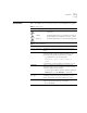
Conventions Conventions 7 Table 1 and Table 2 list conventions that are used throughout this guide.
ABOUT THIS GUIDE Table 2 Text Conventions (continued) Convention Description Words in italics Italics are used to: ■ ■ ■ Emphasize a point. Denote a new term at the place where it is defined in the text. Identify menu names, menu commands, and software button names. Examples: From the Help menu, select Contents. Click OK. Related Documentation This guide is complemented by other 3Com documents and comprehensive help systems.
1 ABOUT DEVICE VIEW Transcend® Device View enables you to monitor and set up the 3Com hubs, switches, bridge/routers, and remote access devices in your enterprise-wide network. This version of the Device View User Guide supplements the information provided in the Device View User Guide included in Transcend Network Control Services, v5.0. See “About This Guide” for the scope of this document and other sources of information.
CHAPTER 1: ABOUT DEVICE VIEW About Device View Device View provides an easy-to-use SNMP-based interface for managing the connectivity devices in your network. Transcend Network Control Services customizes the network management platform to add meaningful symbols to the network map, and associate the symbols that represent manageable devices with applications that support them.
New in This Release New in This Release 11 Transcend NCS v5.0.2 for UNIX includes Device View functionality that enables you to manage the CoreBuilder 9000 Enterprise Switch and the CoreBuilder 9400 Gigabit Ethernet Switch. Management support is shown in Table 3 Table 3 Device View Support for the CoreBuilder 9000 Enterprise Switch Description Agent 3Com Version Part Number 16-slot chassis 3CB9E16 8-slot chassis 3CB9E8 7-slot chassis 3CB9E7 EME (EME1) Enterprise Management Engine 2.
CHAPTER 1: ABOUT DEVICE VIEW This section describes the management features that are available for Small Office and Enterprise Switches, including the CoreBuilder 9000 Enterprise Switch and the CoreBuilder 9400 Gigabit Ethernet Switch. To find information about other 3Com devices, see the Device View User Guide included with TNCS, v5.0. Table 4 shows the small office and enterprise switches that you can manage with Device View.
Management Support Matrix 13 Manage security Set up traps View statistics Create VLANs Create resilient links Manage bridging Manage console port Manage ports Upgrade agent software Use SuperStack groups Set up device Monitor status Table 4 Small Office and Enterprise Switches (continued) (continued) SuperStack II Switch 3000 SuperStack II Switch 3300 SuperStack II Switch IP 3800 SuperStack II Switch 3900 SuperStack II Switch 9000 SX SuperStack II Switch 9300 * Includes CoreBuilder 5000 Toke
CHAPTER 1: ABOUT DEVICE VIEW
2 USING DEVICE VIEW This chapter describes the Device View interface and explains how to run the application and use it to set up manageable devices. This version of the Device View User Guide supplements the information provided in the Device View User Guide included in Transcend Network Control Services, v5.0. See “About This Guide” for the scope of this document and other sources of information.
CHAPTER 2: USING DEVICE VIEW Preparing Devices for Management The ability to set up devices from the SNMP management station is an important part of your configuration management strategy. To prepare to manage devices on your network, you need to perform the following key tasks: 1 Discover devices and create network maps — The management system organizes your network into a hierarchical series of maps and submaps.
Preparing the Management Platform 17 4 Define groups and manage devices — To help you organize managed devices, Device View enables you to create SuperStack groups. You can then select one symbol that represents the devices, and manage all the devices in a single window. 5 Set up IP address of management station — Each device needs to be set up with the IP address of the management station in order to send traps to it.
CHAPTER 2: USING DEVICE VIEW If you add the name of the directory containing the Device View application to your path, you can launch the Device View simply by entering: dv hostname If the device recognizes the community string and can be reached on the network, Device View displays the device. Otherwise, enter: dv -c community_string -device hostname Ensure the device’s community string is correctly set up for the management platform. Device View displays a graphical representation of the device.
Viewing Network Devices Media and Sub Group — Enables you to highlight associated ports. Ports — Select one or more ports with the left mouse button, and click the right mouse button to access a shortcut menu. 19 Modules — Select a module with the left mouse button, and click the right mouse button to access a shortcut menu. Power Supply/Fan (left) — Color indicates status.
CHAPTER 2: USING DEVICE VIEW Managing Media, Modules, Segments, and Ports Device View enables you to set up all aspects of the devices you manage. You can select and work with: ■ Devices ■ Console ports ■ Modules ■ Transceivers ■ Segments ■ Ports ■ Virtual LANs ■ Trunks In many cases, you can choose multiple objects and set them up at the same time.
Managing Media, Modules, Segments, and Ports Using Media Selection Lists 21 Device View also provides two media selection lists called Media and Sub Group which help you to choose the features you want to manage. For example, this makes it easy to work with all Fast Ethernet ports, find out which ports belong to VLAN 2, or choose all the ports that are connected to a cascaded segment in a stack of PS Hub devices as in Figure 2.
CHAPTER 2: USING DEVICE VIEW Viewing and Changing Settings You can access management information about devices, segments, ports, and virtual LANs by highlighting the feature you want to work with and clicking the right mouse button to access a shortcut menu. For modular chassis such as the CoreBuilder 9000 Switch, you can also highlight the entire chassis or a module. The shortcut menu you see depends on the element you have selected.
Managing Media, Modules, Segments, and Ports 23 different section, the tab labels at the top of the page change automatically to show which options are available within that section. The interface for CoreBuilder 5000 and ONline devices uses a single tabbed page for most module and port configuration forms. Device View provides dialog boxes that enable you to read and write management information.
CHAPTER 2: USING DEVICE VIEW Using Online Help This guide introduces you to using Device View to manage 3Com enterprise network equipment in your network. For detailed information about the settings that you can read and set, what fields and controls mean, and how you should use them, refer to the comprehensive online help that is automatically placed on your system when you install Device View.
3 MANAGING DEVICES Device View provides management settings that are appropriate to the feature set of the managed resource. For example, you may need to set up cascaded segments on segmentable hubs, virtual LANs (VLANs) on switches, or ISDN bridging on remote access devices. Device View customizes the interface to match the needs of the systems you are managing.
CHAPTER 3: MANAGING DEVICES Managing CoreBuilder 9000 Switches This section describes the management features that Device View provides for CoreBuilder 9000 Switches in your network. This section contains: Chassis Management ■ Chassis Management ■ Module Management ■ Ethernet Port Setup To manage a CoreBuilder 9000 Switch: 1 View the front of the chassis by starting Device View. 2 Highlight the entire chassis and click the right mouse button.
Managing CoreBuilder 9000 Switches 27 ■ Backplane Connections — Displays a table showing the current backplane connections (switch fabric module to interface module) and the status of each connection. ■ Trunk Setup — Displays a table showing the trunks, and member ports, currently defined on the device. IP Configuration Settings The IP Configuration section contains read-only pages, which are valid for Layer 3 modules only.
CHAPTER 3: MANAGING DEVICES Module Management ■ Temperature — Allows you to view temperature information for a chassis. ■ Fabric — Allows you to view information for the Gigabit Ethernet (GEN) Switch Fabric Module (or modules) operating in the chassis. To manage CoreBuilder 9000 Switch modules: 1 View the front of the chassis by starting Device View. 2 Highlight the module and click the right mouse button. Device View displays a shortcut menu.
Managing CoreBuilder 9000 Switches ■ 29 Backplane Connections — For switch fabric modules, displays a table showing the current backplane connections (switch fabric module to interface module) and the status of each connection. Bridge Settings The Bridge section contains the following settings: ■ General — Allows you to configure standard bridge parameters.
CHAPTER 3: MANAGING DEVICES ■ ARP Cache — Allows you to remove or flush the Address Resolution Protocol (ARP) cache. The ARP cache is a table of IP addresses learned by the device and their corresponding MAC addresses. ■ Interfaces — Allows you to create, edit, and delete IP interfaces. You define interfaces to establish the relationship between the ports on your device and the subnetworks in your IP network. IP interfaces are used for managing the device and to help route packets on your network.
Managing Power Systems 31 Figure 6 Managing Ethernet Ports on High-Function Switches 3 Click Apply after making changes to any settings. The Ports section contains the following settings: Managing Power Systems ■ Ethernet — Enables you to enable, disable, and configure Ethernet ports on a device. ■ Spanning Tree — Allows you to view and configure spanning tree parameters such as the path cost and port priority.
CHAPTER 3: MANAGING DEVICES Managing the CoreBuilder 9000 Switch Power Supply Device View provides you with the following power management features for the CoreBuilder 9000 Switch: ■ You can find out the status of power supplies and fan units, and temperature data for the chassis. ■ You can set Admin Status to Fault Tolerant or Non-Fault Tolerant mode. ■ You can enable or disable Overheat Power Down mode. ■ You can set the Power Class.
Managing Power Systems ■ 33 The EME may shut down selected interface modules in an attempt to bring installed module power consumption under the now-reduced power budget. In power fault-tolerant mode, power equivalent to one power supply is held in reserve. This reserve power is not available to installed modules unless a power supply fails, or if you switch the power mode from power fault-tolerant mode to power non-fault-tolerant mode.
CHAPTER 3: MANAGING DEVICES The following events occur during an overheat condition: 1 The Master EME character display shows the word TEMP 2 If an SNMP agent is present in the chassis, power management informs the SNMP agent of the overheat condition. 3 A 1-minute delay is provided, during which the Master EME and external management entities are notified of the overheat condition.
Managing Power Systems 35 The EME cannot automatically power off a module that is assigned a power class setting of 10. For example, if a power supply failure causes a power deficit (or if a chassis overheat condition develops), a module that is assigned a power class setting of 10 continues to run until you order it to power off. Under some conditions (such as an extended overheat condition), chassis or module hardware damage may result.
CHAPTER 3: MANAGING DEVICES
4 ADVANCED MANAGEMENT TASKS Device View provides you with advanced management capabilities for devices that have special features. For example, you can set up resilient links to safeguard important inter-switch or backbone connections, use the Transcend Load Balancing Tool to optimize the efficiency of PS Hub segments, and view graphical performance statistics.
CHAPTER 4: ADVANCED MANAGEMENT TASKS Viewing Performance Statistics Device View enables you to display a variety of activity and error statistics at device, segment, and port level. The statistics that are available depend on the type of port or device that you select.
Managing Virtual LANs Transcend Network Management Software provides an easy-to-understand graphical interface for setting up and managing virtual LANs (VLANs), allowing network managers to view VLANs within the network, find out about particular VLAN segments, move individuals or groups between segments, and map VLANs to physical device ports.
CHAPTER 4: ADVANCED MANAGEMENT TASKS Policy Based / AutoCast IEEE 802.1Q VLANs AutoSelect VLANs Network-Based VLANs Protocol-Based VLANs Table 6-1 Virtual LAN Support Port-Based VLANs 40 LANplex 6000 SuperStack II Desktop Switch SuperStack II Switch 1000 SuperStack II Switch 1100 SuperStack II Switch 3000 SuperStack II Switch 3300 SuperStack II Switch 3900 SuperStack II Switch 9300 SuperStack II Switch IP 3800 SuperStack II Switch 9000 SX AutoSelect VLANs are supported by agent software version 2.
Managing Virtual LANs 41 Switch 3900, and SuperStack II Switch 9300 devices differ from other 3Com devices. See the Device View online Help to resolve these differences. For the CoreBuilder 9000 Switch, 3Com strongly recommends that you read the CoreBuilder 9000 Implementation Guide for information on VLANs and other features. The kinds of VLAN you can implement are determined by VLAN support in the devices you manage.
CHAPTER 4: ADVANCED MANAGEMENT TASKS interface modules directly; you configure them through the switch fabric module. To create VLANs in the CoreBuilder 9000 environment, you configure these components: ■ Layer 2 and Layer 3 switching modules — You connect to these individually through the EME (Enterprise Management Engine) and configure the following ports based on your VLAN configuration: ■ ■ ■ Front-panel ports — Typically connect external devices to the switching module.
Managing Virtual LANs 43 ports. For example, to create a VLAN for a GEN interface module that resides in chassis slot 6 (when the switch fabric module is installed in slot 8), you could configure the switch fabric module to create a VLAN on backplane ports 11 and 12. Features Your CoreBuilder 9000 supports the VLAN features shown in Table 5.
CHAPTER 4: ADVANCED MANAGEMENT TASKS Table 5 VLAN Features (continued) Feature Ignore STP mode Layer 2 Modules and Switch Layer 3 Fabric Module Modules Description No Yes, in Ignores the blocking Spanning Tree Protocol allClosed (STP) mode for the ports of a designated VLAN. mode (One instance of STP runs on the module, but you can disable it on a per-VLAN basis.) This mode, only available in allClosed mode, is disabled by default.
Managing Virtual LANs IEEE 802.1Q and Per-port Tagging 45 IEEE 802.1Q is a standard for VLANs. It aims to: ■ Define an architecture to logically partition bridged LANs and provide services to defined user groups, independent of physical location ■ Allow interoperability between multivendor equipment. IEEE 802.1Q defines the bridging rules for VLANs (ingress and egress rules).
CHAPTER 4: ADVANCED MANAGEMENT TASKS ■ For backplane ports and switch fabric module ports, you must use tagging when these ports are shared by multiple VLANs. (Only one VLAN’s backplane ports can be untagged; in all other VLANs defined across the backplane, the backplane ports must be tagged.) If you tag the backplane port of a switching module for a VLAN, you must also tag the corresponding switch fabric module port in that VLAN.
Managing Virtual LANs Procedural Guidelines 47 ■ Layer 3 address — On Layer 3 modules, the network or subnetwork address that is associated with a network-based IP VLAN. ■ Port membership — The bridge ports that you assign to be part of the VLAN. If you have created trunks, you must specify the anchor port (lowest-numbered) port in the trunk when you define the VLAN. All bridge ports are initially part of the default VLAN on each module. ■ VLAN name —The name that you assign to the VLAN.
CHAPTER 4: ADVANCED MANAGEMENT TASKS the lower-numbered backplane port. (Example: On a 10-port Layer 2 switching module, you configure port 11; on a 12-port Layer 3 module, you configure port 13.) When you have multiple VLANs, tag the backplane port. (In a subsequent step, you must tag the associated switch fabric module backplane port as well.) 4 On each Layer 3 switching module with VLANs that you want to perform routing, define a routing interface for each protocol-based or network-based VLAN.
Managing Virtual LANs 49 Device View does not provide a single dialog box, listing all ports on all modules in the chassis, through which you can create a port-based VLAN that spans multiple modules. To do this, you must follow these general steps: 1 Access each module that contains ports you want to include in the VLAN. 2 Create a VLAN on each individual module and assign the same VLAN ID to each VLAN. Be sure to include the module's backplane port in the VLAN.
CHAPTER 4: ADVANCED MANAGEMENT TASKS Ports in the VLAN are highlighted. 3 View VLAN information about the highlighted ports by clicking the right mouse button, choosing Configure from the shortcut menu, and clicking the VLAN tab. Creating, Editing, or Deleting VLANs To create, edit, or delete a VLAN: 1 Select a switch module. 2 Click the right mouse button and choose Config Module from the shortcut menu. 3 Click the VLAN tab. 4 Click the appropriate button: Create, Edit, or Delete.
INDEX INDEX VLANs 40 S C CoreBuilder 2500 statistics 38 VLANs 39 3500 statistics 38 VLANs 39 5000 VLANs 39 6000 VLANs 39 9000 management features 12 management options 26 power management 32 statistics 38 support 12 supported modules 11 VLANs 39 9400 statistics 38 support 12 VLANs 39 D Device View accessing online Help 24 new features 11 overview 10 starting 17 Devices perparing to manage 16 viewing 18 viewing and changing settings 22 L LANplex 2016 statistics 38 2500 VLANs 39 6000 SuperStack II Adva
INDEX