6954ua.book Page 1 Friday, April 30, 1999 9:39 AM ® SuperStack® II Switch 610 User Guide 3C16954 http://www.3com.com/ Part No.
16954ua.book Page 2 Friday, April 30, 1999 9:39 AM 3Com Corporation 5400 Bayfront Plaza Santa Clara, California 95052-8145 Copyright © 1999, 3Com Technologies. All rights reserved. No part of this documentation may be reproduced in any form or by any means or used to make any derivative work (such as translation, transformation, or adaptation) without written permission from 3Com Technologies.
16954ua.
16954ua.
16954ua.
16954ua.
16954ua.book Page 7 Friday, April 30, 1999 9:39 AM ABOUT THIS GUIDE This guide provides all the information you need to install and use a SuperStack ® II Switch 610 unit with default settings. If you want to change the way the Switch works using management software, refer to the “SuperStack II Switch Management Guide” (part number DUA1695-0BAA0x).
16954ua.book Page 8 Friday, April 30, 1999 9:39 AM 8 ABOUT THIS GUIDE Conventions Table 1 and Table 2 list conventions that are used throughout this guide.
16954ua.book Page 9 Friday, April 30, 1999 9:39 AM Related Documentation 9 Table 2 Text Conventions (continued) Convention Description Words in italics Italics are used to: ■ ■ ■ Emphasize a point. Denote a new term at the place where it is defined in the text. Identify menu names, menu commands, and software button names. Examples: From the Help menu, select Contents. Click OK.
16954ua.book Page 10 Friday, April 30, 1999 9:39 AM 10 ABOUT THIS GUIDE Year 2000 Compliance For information on Year 2000 compliance and 3Com products, visit the 3Com Year 2000 Web page: http://www.3com.com/products/yr2000.html Documentation Comments Your suggestions are very important to us. They will help make our documentation more useful to you. Please e-mail comments about this document to 3Com at: pddtechpubs_comments@3com.
16954ua.book Page 11 Friday, April 30, 1999 9:39 AM 1 INTRODUCING THE SWITCH 610 This chapter contains introductory information about the Switch and how it can be used in your network.
16954ua.book Page 12 Friday, April 30, 1999 9:39 AM 12 CHAPTER 1: INTRODUCING THE SWITCH 610 About the SuperStack II Switch 610 The SuperStack® II system solves the problem of growth in dynamic network environments and provides everything you need for successful workgroup networking. Much more than a collection of stackable components, the system comprises a complete, integrated architecture of modular parts that are easy to install and use.
16954ua.book Page 13 Friday, April 30, 1999 9:39 AM Switch 610 — Front View Detail 13 Switch 610 — Front View Detail Figure 1 Switch 610 — Front view Port Connections 10BASE-T Ports The Switch has 24 10BASE-T ports configured as MDIX (cross-over). The maximum segment length is 100m (328ft) over Category 3, 4, or 5 twisted pair cable. As these ports are configured as MDIX (cross-over), you need to use a cross-over cable to connect to devices whose ports are MDIX-only.
16954ua.book Page 14 Friday, April 30, 1999 9:39 AM 14 CHAPTER 1: INTRODUCING THE SWITCH 610 LEDs Table 3 lists the LEDs visible on the front of the Switch, and their states according to color. For information on using the LEDs for problem solving, see “Checking for Correct Operation” on page 24. Table 3 LED behavior LED Color Indicates Port Status LEDs Packet Status Yellow Packets are being transmitted/received on the port. Off No packets are being transmitted/received on the port.
16954ua.book Page 15 Friday, April 30, 1999 9:39 AM Switch 610 — Rear View Detail 15 Switch 610 — Rear View Detail Figure 2 Switch 610 — Rear view Unit Information Label This label shows the following: ■ The 3Com product name of the Switch ■ The 3Com 3C number of the Switch ■ The unique MAC address (Ethernet address) of the Switch ■ The serial number of the Switch You may need this information for fault reporting purposes.
954ua.book Page 16 Friday, April 30, 1999 9:39 AM 16 CHAPTER 1: INTRODUCING THE SWITCH 610 Network Configuration Examples Network Segmentation I The following illustrations show some examples of how the Switch can be placed on your network. Figure 3 shows how the Switch 610 fits into a large corporate network with a Fast Ethernet infrastructure. A Switch is positioned on each floor and servers are centralized in the basement.
16954ua.book Page 17 Friday, April 30, 1999 9:39 AM Network Configuration Examples Network Segmentation II 17 Figure 4 shows the Switch 610 in a second workgroup situation. This setup could be that of a small office within a large corporation, or part of a larger corporate network. Most of the switch ports have multiple endstations.
16954ua.book Page 18 Friday, April 30, 1999 9:39 AM 18 CHAPTER 1: INTRODUCING THE SWITCH 610 Desktop Switching Figure 5 shows the Switch 610 used for a group of users in a large corporate network. Here switching is brought to the desktop with a single endstation per port. Local servers are connected via 100Mbps Fast Ethernet links.
16954ua.book Page 19 Friday, April 30, 1999 9:39 AM Configuration Rules for Fast Ethernet Configuration Rules for Fast Ethernet 19 The topology rules for 100Mbps Fast Ethernet are slightly different to those for 10Mbps Ethernet. Figure 6 illustrates the key topology rules and provides examples of how they allow for large-scale Fast Ethernet networks.
16954ua.book Page 20 Friday, April 30, 1999 9:39 AM 20 CHAPTER 1: INTRODUCING THE SWITCH 610 The key topology rules are: Configuration Rules with Full Duplex ■ Maximum UTP cable length is 100m (328ft) over Category 5 cable. ■ A 412m (1352ft) fiber run is allowed for connecting switch-to-switch, or endstation-to-switch, using half-duplex 100BASE-FX.
16954ua.book Page 21 Friday, April 30, 1999 9:39 AM 2 INSTALLING THE SWITCH This chapter contains the information you need to install and set up the Switch. It covers the following topics: ■ Choosing a Suitable Site ■ Rack-mounting ■ Placing Units On Top of Each Other ■ The Power-up Sequence ■ Choosing the Correct Cables ■ Solving Problems Indicated by LEDs ■ Managing the Switch WARNING: Safety Information.
16954ua.book Page 22 Friday, April 30, 1999 9:39 AM 22 CHAPTER 2: INSTALLING THE SWITCH Choosing a Suitable Site The Switch is suited for use in an office environment where it can be mounted in a standard 19-inch equipment rack, or free standing. Alternatively, the Switch can be rack-mounted in a wiring closet or equipment room. A rack-mounting kit, containing two mounting brackets and six screws, is supplied with the Switch.
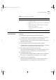
16954ua.book Page 23 Friday, April 30, 1999 9:39 AM Placing Units On Top of Each Other 23 Figure 7 Fitting a bracket for rack mounting 3 Insert the two screws and tighten with a suitable screwdriver. You must use the screws supplied with the mounting brackets. Damage caused to the unit by using incorrect screws invalidates your warranty. 4 Repeat steps 2 and 3 for the other side of the Switch. 5 Insert the Switch into the 19-inch rack and secure with suitable screws (not provided).
16954ua.book Page 24 Friday, April 30, 1999 9:39 AM 24 CHAPTER 2: INSTALLING THE SWITCH The Power-up Sequence Connecting a Redundant Power System The following sections describe how to get your Switch 610 powered-up and ready for operation. You can connect a SuperStack II Advanced Redundant Power System (part number 3C16071) to the Switch. This unit, which is also known as an RPS, is designed to maintain the power to your Switch if a power supply failure occurs.
16954ua.book Page 25 Friday, April 30, 1999 9:39 AM Choosing the Correct Cables Choosing the Correct Cables 25 All of the ports on the front of the Switch 610 are configured as MDIX (cross-over). If you want to make a connection to another MDIX port, you need a cross-over cable. Most of the 10BASE-T and 100BASE-TX ports on 3Com devices are MDIX-only. Many ports on workstations and servers are configured as MDI (straight-through).
16954ua.book Page 26 Friday, April 30, 1999 9:39 AM 26 CHAPTER 2: INSTALLING THE SWITCH Table 5 Problems indicated by LEDs Problem Suggested Solution A link is connected and Check that: yet the Status LED for ■ All connections are secure. the port does not light ■ The devices at both ends of the link are powered-up.
16954ua.book Page 27 Friday, April 30, 1999 9:39 AM A SAFETY INFORMATION You must read the following safety information before carrying out any installation or removal of components, or any maintenance procedures on the Switch 610. WARNING: Warnings contain directions that you must follow for your personal safety. Follow all directions carefully. You must read the following safety information carefully before you install or remove the unit.
16954ua.book Page 28 Friday, April 30, 1999 9:39 AM 28 APPENDIX A: SAFETY INFORMATION Important Safety Information ■ Installation and removal of the unit must be carried out by qualified personnel only. ■ If installing the Switch unit in a stack with SuperStack II Hub units, the Switch 610 unit must be installed below the narrower Hub units. ■ The unit should never be connected to an A.C. outlet (power supply) without an earth (ground) connection.
16954ua.book Page 29 Friday, April 30, 1999 9:39 AM Important Safety Information 29 ■ France and Peru only: This unit cannot be powered from IT† supplies. If your supplies are of IT type, this unit must be powered by 230V (2P+T) via an isolation transformer ratio 1:1, with the secondary connection point labelled Neutral, connected directly to earth (ground). †Impédance à la terre.
16954ua.book Page 30 Friday, April 30, 1999 9:39 AM 30 APPENDIX A: SAFETY INFORMATION L’information de Sécurité Importante ■ L'installation et la dépose de ce groupe doivent être confiés à un personnel qualifié. ■ Si vous entassez l'unité Switch avec les unités SuperStack II Hub, l'unité Switch 610 doit être installée en dessous des unités Hub plus étroites. ■ L’unité ne devrait pas etre branchee a une prise de courant C.A.
16954ua.book Page 31 Friday, April 30, 1999 9:39 AM L’information de Sécurité Importante 31 ■ L’appareil fonctionne à une tension extrêmement basse de sécurité qui est conforme à la norme CEI 950. Ces conditions ne sont maintenues que si l'équipement auquel il est raccordé fonctionne dans les mêmes conditions. ■ France et Pérou uniquement: Ce groupe ne peut pas être alimenté par un dispositif à impédance à la terre.
16954ua.book Page 32 Friday, April 30, 1999 9:39 AM 32 APPENDIX A: SAFETY INFORMATION Wichtige Sicherheitsinformationen ■ Die Installation und der Ausbau des Geräts darf nur durch Fachpersonal erfolgen. ■ Wenn die Switch 610 Einheit in einer Stapel mit anderen SuperStack II Hub Einheiten eingebaut werden soll, muß die Switch 610 Einheit unter die schmaleren Hub Einheiten eingebaut werden. ■ Das Gerät ist unter keinen umständen an einen Wechselstrom (A.C.
16954ua.
16954ua.
16954ua.book Page 35 Friday, April 30, 1999 9:39 AM C TECHNICAL SPECIFICATIONS Physical Dimensions Height: 44mm (1.7 in.) x Width: 440mm (17.3 in.) x Depth 224mm (8.8 in.) Weight: 4.4kg (9.7lbs) Environmental Requirements Operating Temperature 0° to 50°C (32° to 122°F) Storage Temperature –10° to +70°C (14° to 158°F) Operating Humidity 10 to 95% relative humidity, non-condensing Standards EN60068 (IEC68) Safety Agency Certifications UL 1950, EN60950, CSA 22.2 No.
16954ua.book Page 36 Friday, April 30, 1999 9:39 AM 36 APPENDIX C: TECHNICAL SPECIFICATIONS Standards Supported SNMP Terminal Emulation ■ SNMP protocol (RFC 1157) ■ ■ MIB-II (RFC 1213) Protocols Used for Administration ■ Bridge MIB (RFC 1493) ■ UDP (RFC 768) ■ Repeater MIB (RFC 1516) ■ IP (RFC 791) ■ RMON MIB (RFC 1271) ■ ICMP (RFC 792) ■ BOOTP (RFC 951) ■ TCP (RFC 793) ■ ARP (RFC 826) ■ TFTP (RFC 783) Additional Standards Supported ■ ISO/IEC 15802-3-1998 (IEEE 802.
16954ua.book Page 37 Friday, April 30, 1999 9:39 AM D TECHNICAL SUPPORT 3Com provides easy access to technical support information through a variety of services. This appendix describes these services. Information contained in this appendix is correct at time of publication. For the most recent information, 3Com recommends that you access the 3Com Corporation World Wide Web site.
16954ua.book Page 38 Friday, April 30, 1999 9:39 AM 38 APPENDIX D: TECHNICAL SUPPORT 3Com FTP Site Download drivers, patches, software, and MIBs across the Internet from the 3Com public FTP site. This service is available 24 hours a day, 7 days a week. To connect to the 3Com FTP site, enter the following information into your FTP client: ■ Hostname: ftp.3com.
16954ua.book Page 39 Friday, April 30, 1999 9:39 AM Support from Your Network Supplier 39 Access by Digital Modem ISDN users can dial in to the 3Com BBS using a digital modem for fast access up to 64 Kbps. To access the 3Com BBS using ISDN, call the following number: 1 847 262 6000 3Com Facts Automated Fax Service The 3Com Facts automated fax service provides technical articles, diagrams, and troubleshooting instructions on 3Com products 24 hours a day, 7 days a week.
16954ua.
16954ua.book Page 41 Friday, April 30, 1999 9:39 AM Returning Products for Repair Returning Products for Repair 41 Before you send a product directly to 3Com for repair, you must first obtain an authorization number. Products sent to 3Com without authorization numbers will be returned to the sender unopened, at the sender’s expense.
16954ua.
16954ua.book Page 43 Friday, April 30, 1999 9:39 AM GLOSSARY 10BASE-T The IEEE specification for 10Mbps Ethernet over Category 3, 4 or 5 twisted pair cable. 100BASE-FX The IEEE specification for 100Mbps Fast Ethernet over fiber-optic cable. 100BASE-TX The IEEE specification for 100Mbps Fast Ethernet over Category 5 twisted-pair cable. auto-negotiation A feature on twisted pair ports that allows them to advertise their capabilities for speed, duplex and flow control.
16954ua.book Page 44 Friday, April 30, 1999 9:39 AM 44 GLOSSARY broadcast storm Multiple simultaneous broadcasts that typically absorb all the available network bandwidth and can cause a network to fail. Broadcast storms can be due to faulty network devices. collision A term used to describe two colliding packets in an Ethernet network.
16954ua.book Page 45 Friday, April 30, 1999 9:39 AM GLOSSARY 45 hub A device that regenerates LAN traffic so that the transmission distance of that signal can be extended. Hubs are similar to repeaters, in that they connect LANs of the same type; however they connect more LANs than a repeater and are generally more sophisticated. IEEE Institute of Electrical and Electronics Engineers. This American organization was founded in 1963 and sets standards for computers and communications. IEEE 802.
16954ua.book Page 46 Friday, April 30, 1999 9:39 AM 46 GLOSSARY MAC address Media Access Control address; also called hardware or physical address. A layer 2 address associated with a particular network device. Most devices that connect to a LAN have a MAC address assigned to them as they are used to identify other devices in a network. MAC addresses are 6 bytes long. MDI Medium Dependent Interface.
16954ua.book Page 47 Friday, April 30, 1999 9:39 AM GLOSSARY SNMP 47 Simple Network Management Protocol. The current IETF standard protocol for managing devices on an TCP/IP network. stack A group of network devices that are integrated to form a single logical device. switch A device that interconnects several LANs to form a single logical LAN that comprises of several LAN segments.
16954ua.
16954ua.book Page 49 Friday, April 30, 1999 9:39 AM INDEX INDEX H hardware features 12 I installing the Switch 21 prerequisites 22 Numerics 10BASE-T ports 13 10BASE-T/100BASE-TX ports 13 3C number 15 3Com bulletin board service (3Com BBS) 38 3Com Knowledgebase Web Services 37 3Com URL 37 3ComFacts 39 A auto-negotiating ports 13 B bulletin board service 38 L LEDs 14 Light Emitting Diodes.
16954ua.book Page 50 Friday, April 30, 1999 9:39 AM 50 INDEX Redundant Power System. See RPS returning products for repair 41 RPS 15 connecting 24 socket 15 fax service 39 network suppliers 39 product repair 41 topology rules for Fast Ethernet 19 topology rules with full duplex 20 S U safety information English 28 French 30 German 32 segment, maximum length 13, 20 serial number of the Switch 15 serial port.
16954ua.
16954ua.book Page 52 Friday, April 30, 1999 9:39 AM product, but may be delayed due to export or import procedures. When an advance replacement is provided and Customer fails to return the original product to 3Com within fifteen (15) days after shipment of the replacement, 3Com will charge Customer for the replacement product, at list price.
16954ua.book Page 53 Friday, April 30, 1999 9:39 AM EMC STATEMENTS FCC STATEMENT This equipment has been tested and found to comply with the limits for a Class A digital device, pursuant to part 15 of the FCC rules. These limits are designed to provide reasonable protection against harmful interference when the equipment is operated in a commercial environment.
16954ua.