DUA1720-3AAA07.book Page 1 Wednesday, March 17, 2004 1:14 PM SuperStack® 3 Switch 4400 Series Getting Started Guide Switch 4400 (3C17203) Switch 4400 (3C17204) Switch 4400 PWR (3C17205) Switch 4400 SE (3C17206) Switch 4400 FX (3C17210) http://www.3com.com/ Part No.
DUA1720-3AAA07.book Page 2 Wednesday, March 17, 2004 1:14 PM 3Com Corporation 350 Campus Drive Marlborough, MA 01752-3064 Copyright © 2004, 3Com Corporation. All rights reserved. No part of this documentation may be reproduced in any form or by any means or used to make any derivative work (such as translation, transformation, or adaptation) without written permission from 3Com Corporation.
DUA1720-3AAA07.
DUA1720-3AAA07.
DUA1720-3AAA07.
DUA1720-3AAA07.
DUA1720-3AAA07.book Page 7 Wednesday, March 17, 2004 1:14 PM ABOUT THIS GUIDE This guide provides all the information you need to install and use the following switches in their default state: ■ SuperStack® 3 Switch 4400 (3C17203) ■ SuperStack® 3 Switch 4400 (3C17204) ■ SuperStack® 3 Switch 4400 PWR (3C17205) ■ SuperStack® 3 Switch 4400 SE (3C17206) ■ SuperStack® 3 Switch 4400 FX (3C17210) All procedures described in this guide apply to all models except where stated.
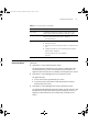
DUA1720-3AAA07.book Page 8 Wednesday, March 17, 2004 1:14 PM 8 ABOUT THIS GUIDE About Your CD-ROM The CD-ROM contains the following: ■ Online documentation for the Switch 4400 — refer to Related Documentation on page 9 for details. ■ 3Com Network Supervisor — a powerful and easy-to-use network management platform. ■ A number of other useful applications.
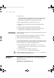
DUA1720-3AAA07.book Page 9 Wednesday, March 17, 2004 1:14 PM Related Documentation 9 Table 2 Text Conventions (continued) Convention The words “enter” and “type” Description When you see the word “enter” in this guide, you must type something, and then press Return or Enter. Do not press Return or Enter when an instruction simply says “type.” Keyboard key names If you must press two or more keys simultaneously, the key names are linked with a plus sign (+).
DUA1720-3AAA07.book Page 10 Wednesday, March 17, 2004 1:14 PM 10 ABOUT THIS GUIDE ■ Release Notes These notes provide information about the current software release, including new features, modifications, and known problems. The Release Notes are supplied in hard copy with your Switch. There are other publications you may find useful, such as: Accessing Online Documentation ■ Documentation accompanying the Advanced Redundant Power system. ■ Documentation accompanying the Expansion Modules.
DUA1720-3AAA07.book Page 11 Wednesday, March 17, 2004 1:14 PM Product Registration 11 Please include the following information when commenting: ■ Document title ■ Document part number (on the title page) ■ Page number (if appropriate) Example: Part Number DUA1720-3AAA07 SuperStack 3 Switch 4400 Series Getting Started Guide Page 21 Please note that we can only respond to comments and questions about 3Com product documentation at this e-mail address.
DUA1720-3AAA07.
DUA1720-3AAA07.book Page 13 Wednesday, March 17, 2004 1:14 PM 1 INTRODUCING THE SUPERSTACK 3 SWITCH 4400 This chapter contains introductory information about the Switch 4400 and how it can be used in your network.
DUA1720-3AAA07.book Page 14 Wednesday, March 17, 2004 1:14 PM 14 CHAPTER 1: INTRODUCING THE SUPERSTACK 3 SWITCH 4400 About the Switch 4400 The Switch 4400 is a stackable 10/100 Mbps Ethernet switch and provides high-performance workgroups with a backbone to server connection. The Switch 4400 allows Cascade, Gigabit Ethernet or Fast Ethernet Fiber connections when expansion modules are installed in the expansion slots on the rear of the unit.
DUA1720-3AAA07.
DUA1720-3AAA07.book Page 16 Wednesday, March 17, 2004 1:14 PM 16 CHAPTER 1: INTRODUCING THE SUPERSTACK 3 SWITCH 4400 Figure 4 Switch 4400 (48-port) — front view WARNING: RJ-45 Ports. These are shielded RJ-45 data sockets. They cannot be used as standard traditional telephone sockets, or to connect the unit to a traditional PBX or public telephone network. Only connect RJ-45 data connectors, network telephony systems, or network telephones to these sockets.
DUA1720-3AAA07.book Page 17 Wednesday, March 17, 2004 1:14 PM Switch 4400 — Front View Detail 17 connector that allows both the transmit and the receive fibers to be connected in the same space as an RJ-45 port. LEDs Table 4 lists LEDs visible on the front of the Switch, and how to read their status according to color. For information on using the LEDs for problem solving, see “Solving Problems Indicated by LEDs” on page 58.
DUA1720-3AAA07.book Page 18 Wednesday, March 17, 2004 1:14 PM 18 CHAPTER 1: INTRODUCING THE SUPERSTACK 3 SWITCH 4400 LED Color Indicates Port LEDs — Power over Ethernet mode (3C17205 only) Packet Green Power is being delivered to the port. Green flashing Exceeded port power limit (overCurrent MIB state) or unable to supply power due to unit over budget (denyLowPriority MIB state). Yellow Power over Ethernet error, no power supplied on port. Off No power is being delivered.
DUA1720-3AAA07.book Page 19 Wednesday, March 17, 2004 1:14 PM Switch 4400 — Rear View Detail Switch 4400 — Rear View Detail Power Socket 19 Figure 5 Switch 4400 (all models) — rear view The Switch automatically adjusts its power setting to any supply voltage in the range 90-240 VAC. Redundant Power System Socket To protect against internal power supply failure, you can use this socket to connect a Switch 4400 to a SuperStack 3 Advanced Redundant Power System (RPS).
DUA1720-3AAA07.
DUA1720-3AAA07.book Page 21 Wednesday, March 17, 2004 1:14 PM Default Settings 21 To make SSH, Webcache redirection, RADIUS (including 802.1x Network Login), Auto VLAN assignment, and Traffic Prioritization available on the SuperStack 3 Switch 4400 SE, upgrade the product to the Switch 4400 SE Enhanced Software Upgrade (3C17207).
DUA1720-3AAA07.
DUA1720-3AAA07.book Page 23 Wednesday, March 17, 2004 1:14 PM 2 INSTALLING THE SWITCH This chapter contains the information you need to install and set up the Switch 4400. It covers the following topics: ■ ■ ■ ■ ■ ■ Package Contents Choosing a Suitable Site Rack-mounting Placing Units On Top of Each Other Stacking Units The Power-up Sequence WARNING: Safety Information.
DUA1720-3AAA07.
DUA1720-3AAA07.book Page 25 Wednesday, March 17, 2004 1:14 PM Rack-mounting Rack-mounting 25 ■ The air is as free from dust as possible. ■ The unit is installed in a clean, air conditioned environment. ■ No more than eight Switch units are placed on top of one another, if the units are free-standing. ■ The Switch is situated away from sources of conductive (electrical) dust, for example laser printers.
DUA1720-3AAA07.book Page 26 Wednesday, March 17, 2004 1:14 PM 26 CHAPTER 2: INSTALLING THE SWITCH Figure 6 Fitting a bracket for rack-mounting 3 Insert the two screws and tighten with a suitable screwdriver. You must use the screws supplied with the mounting brackets. Damage caused to the unit by using incorrect screws invalidates your warranty. 4 Repeat steps 2 and 3 for the other side of the Switch. 5 Insert the Switch into the 19-inch rack and secure with suitable screws (not provided).
DUA1720-3AAA07.book Page 27 Wednesday, March 17, 2004 1:14 PM Placing Units On Top of Each Other Placing Units On Top of Each Other 27 If the Switch units are free-standing, up to eight units can be placed one on top of the other. If you are mixing a variety of SuperStack® 3 Switch and Hub units, the smaller units must be positioned at the top. If you are placing Switch units one on top of the other, you must use the self-adhesive rubber pads supplied.
DUA1720-3AAA07.book Page 28 Wednesday, March 17, 2004 1:14 PM 28 CHAPTER 2: INSTALLING THE SWITCH Cascade Extender Unit. The Cascade Module is installed into the expansion slot at the rear of the Switch and the Cascade Extender Unit plugs into the Cascade Module.
DUA1720-3AAA07.book Page 29 Wednesday, March 17, 2004 1:14 PM Stacking Units 29 ■ The Cascade Extender Unit is hot-insertable. This allows its host Switch unit to be removed and replaced without disturbing the rest of the stack. ■ Only 3Com® Cascade Cables can be used to connect between Cascade Modules/Cascade Extender Units.
DUA1720-3AAA07.book Page 30 Wednesday, March 17, 2004 1:14 PM 30 CHAPTER 2: INSTALLING THE SWITCH The Power-up Sequence Powering-up the Switch 4400 The following sections describe how to get your Switch 4400 powered-up and ready for operation. Use the following sequence of steps to power-up the Switch. 1 Plug the power cord into the power socket at the rear of the Switch. 2 Plug the other end of the power cord into your power outlet.
DUA1720-3AAA07.book Page 31 Wednesday, March 17, 2004 1:14 PM The Power-up Sequence 31 CAUTION The Switch has no ON/OFF switch; the only method of connecting or disconnecting mains power is by connecting or disconnecting the power cord. CAUTION: The Switch can only use a SuperStack Advanced Redundant Power System output. Using Power over Ethernet The Switch 4400 PWR can power any IEEE 802.3af compliant device through any of its front panel ports. The Switch will support the following 3Com 802.
DUA1720-3AAA07.
DUA1720-3AAA07.book Page 33 Wednesday, March 17, 2004 1:14 PM The Power-up Sequence 33 connection to an MDI port, you need to use a standard straight-through cable. See Table 7. WARNING: The 4400 PWR (3C17205) supports Power over Ethernet on all front ports. These ports should only be used for Ethernet wiring within the same building. The Rear Module ports of the Switch 4400 PWR can be used for ethernet wiring between buildings.
DUA1720-3AAA07.book Page 34 Wednesday, March 17, 2004 1:14 PM 34 CHAPTER 2: INSTALLING THE SWITCH Auto-MDIX sensing is required. The maximum cable length is 2 kilometers (1.24 miles). CAUTION: Do not connect pinned MT-RJ connectors into any port on the Switch 4400 FX as this may damage the unit. The ports have locator pins fitted and are designed for standard (pinless) connectors.
DUA1720-3AAA07.book Page 35 Wednesday, March 17, 2004 1:14 PM 3 SETTING UP FOR MANAGEMENT Your Switch can operate in its default state, that is, you can install it and it will work straight away (plug-and-play). However, to make full use of the features offered by the Switch, and to change and monitor the way it works, you have to access the management software that resides on the Switch. This is known as managing the Switch.
DUA1720-3AAA07.book Page 36 Wednesday, March 17, 2004 1:14 PM CHAPTER 3: SETTING UP FOR MANAGEMENT This section gives an overview of what you need to do to get your Switch set up and ready for management when it is in its default state. The whole setup process is summarized in Figure 9. Detailed procedural steps are contained in the sections that follow.
DUA1720-3AAA07.book Page 37 Wednesday, March 17, 2004 1:14 PM Setting Up Overview 37 CAUTION: To protect your Switch from unauthorized access, you must change all three default passwords as soon as possible, even if you do not intend to actively manage your Switch. For more information on default users and changing default passwords, see “Default Users and Passwords” on page 55.
DUA1720-3AAA07.book Page 38 Wednesday, March 17, 2004 1:14 PM 38 CHAPTER 3: SETTING UP FOR MANAGEMENT This process is known as Auto-IP and is the same mechanism used by Windows 98 and Windows 2000. IP addresses configured by Auto-IP are temporary as they cannot be routed but are useful for small networks which are not connected to other networks, or for initial configuration.
DUA1720-3AAA07.book Page 39 Wednesday, March 17, 2004 1:14 PM Manually Configuring IP Information Manually Configuring IP Information Connecting to a Front Panel Port 39 You can manually configure the Switch IP information in the following ways: ■ Connecting to a front panel port — Connect a workstation using an Ethernet cable to a front panel port of the Switch. You can then manually enter IP information using the web interface or the command line interface (CLI).
DUA1720-3AAA07.book Page 40 Wednesday, March 17, 2004 1:14 PM 40 CHAPTER 3: SETTING UP FOR MANAGEMENT Connecting the Workstation to the Switch 1 Connect the workstation to a front panel port using an Ethernet cable as shown in Figure 10. Figure 10 Connecting a workstation to the Switch via a front panel port To connect the cable: a Attach an RJ-45 connector at one end of the Ethernet cable to the Network Interface Card (NIC) in the workstation.
DUA1720-3AAA07.book Page 41 Wednesday, March 17, 2004 1:14 PM Manually Configuring IP Information 41 If there is no response, wait for one minute then re-enter the default IP address. 3 At the login and password prompts, enter admin as your user name and press Return at the password prompt (default user name and password). If you have logged on correctly, a set of Getting Started pages are displayed. 4 The Getting Started pages allow you to enter basic setup information for the Switch.
DUA1720-3AAA07.book Page 42 Wednesday, March 17, 2004 1:14 PM 42 CHAPTER 3: SETTING UP FOR MANAGEMENT Figure 11 Example top-level command line interface menu 4 At the Select menu option prompt you can either: ■ enter the protocol ip basicConfig command. At the Enter configuration method prompt enter manual. The screen prompts you to enter IP information. or ■ enter the gettingStarted command. At the Enter configuration method prompt enter manual. The screen prompts you to enter IP information.
DUA1720-3AAA07.book Page 43 Wednesday, March 17, 2004 1:14 PM Manually Configuring IP Information 43 Pre-requisites ■ A workstation with terminal emulation software installed, such as Microsoft Hyperterminal. This software allows you to communicate with the Switch via the console port directly, or through a modem. ■ Documentation supplied with the terminal emulation software.
DUA1720-3AAA07.book Page 44 Wednesday, March 17, 2004 1:14 PM 44 CHAPTER 3: SETTING UP FOR MANAGEMENT 2 Open your terminal emulation software and configure the COM port settings to which you have connected the cable. The settings should be set to match the default settings for the Switch, which are: ■ 19,200 baud ■ 8 data bits ■ no parity ■ 1 stop bit ■ no hardware flow control Refer to the documentation that accompanies the terminal emulation software for more information.
DUA1720-3AAA07.book Page 45 Wednesday, March 17, 2004 1:14 PM Manually Configuring IP Information 45 Figure 13 Example top-level command line interface menu 3 At the Select menu option prompt you can either: ■ enter the protocol ip basicConfig command. At the Enter configuration method prompt enter manual. The screen prompts you to enter IP information. or ■ enter the gettingStarted command. At the Enter configuration method prompt enter manual. The screen prompts you to enter IP information.
DUA1720-3AAA07.book Page 46 Wednesday, March 17, 2004 1:14 PM 46 CHAPTER 3: SETTING UP FOR MANAGEMENT Viewing Automatically Configured IP Information Using 3Com Network Supervisor If you allow the Switch to automatically configure its own IP information you need to discover and view the IP information before you can begin to manage the Switch.
DUA1720-3AAA07.book Page 47 Wednesday, March 17, 2004 1:14 PM Viewing Automatically Configured IP Information ■ 47 A suitable cable: ■ ■ A standard null modem cable — if you are connecting directly to the console port, or A standard modem cable — if you are connecting to the console port using a modem. You can find pin-out diagrams for both cables in Appendix B on page 73. ■ A Category 5 twisted pair Ethernet cable with RJ-45 connectors to connect your Switch to the network.
DUA1720-3AAA07.book Page 48 Wednesday, March 17, 2004 1:14 PM 48 CHAPTER 3: SETTING UP FOR MANAGEMENT Viewing IP Information via the Console Port You are now ready to view the automatically allocated IP information using the command line interface. 1 Connect your Switch to the network using an Ethernet cable. As soon as a network connection is made the Switch begins the automatic IP configuration process. The automatic IP configuration process usually completes within one minute.
DUA1720-3AAA07.book Page 49 Wednesday, March 17, 2004 1:14 PM Methods of Managing a Switch 49 The initial set up of your Switch is now complete and the Switch is ready for you to set up your chosen management method. See “Methods of Managing a Switch” on page 49. If you do not intend to use the command line interface via the console port to manage the Switch, you can logout, disconnect the serial cable and close the terminal emulator software.
DUA1720-3AAA07.book Page 50 Wednesday, March 17, 2004 1:14 PM 50 CHAPTER 3: SETTING UP FOR MANAGEMENT Command Line Interface Management using SSH Web Interface Management The Switch 4400 supports Secure Shell version 2 (SSHv2), allowing secure access to the Command Line Interface of the Switch. If you use SSH to administer your Switch and the network traffic is intercepted, no passwords or configuration information will be visible in the data.
DUA1720-3AAA07.book Page 51 Wednesday, March 17, 2004 1:14 PM Setting Up Command Line Interface Management CLI Management via the Console Port 51 To manage a Switch using the command line interface via the local console port connection: 1 Ensure you have connected your workstation to the console port correctly as described in “Connecting to the Console Port” on page 42. 2 Your Switch is now ready to continue being managed and/or configured through the CLI via its console port.
DUA1720-3AAA07.book Page 52 Wednesday, March 17, 2004 1:14 PM 52 CHAPTER 3: SETTING UP FOR MANAGEMENT Setting Up Command Line Interface Management using SSH This section describes how you can set up Command Line Interface management using SSH over a network. To manage a Switch using the command line interface over a network using SSH: 1 Ensure you have already set up the Switch with IP information as described in “Setting Up Overview” on page 36.
DUA1720-3AAA07.book Page 53 Wednesday, March 17, 2004 1:14 PM Setting Up Web Interface Management 53 For further information on generating a host key on your switch and transferring keys to the Switch using TFTP server please refer to Chapter 11 of the “SuperStack 3 Switch Implementation Guide”. Setting Up Web Interface Management This section describes how you can set up web interface management over the network.
DUA1720-3AAA07.book Page 54 Wednesday, March 17, 2004 1:14 PM 54 CHAPTER 3: SETTING UP FOR MANAGEMENT ■ Variable Width Font - Size 10.0 ■ Fixed Width Font - Size 12.0 This ensures that the text spacing is correct. Finally in the Advanced category ensure that Enable Java Script and Enable style sheets are checked. Web Management Over the Network To manage a Switch using the web interface over an IP network: 1 Check that you have the IP protocol correctly installed on your management workstation.
DUA1720-3AAA07.book Page 55 Wednesday, March 17, 2004 1:14 PM Default Users and Passwords 55 automatically loads the correct MIBs and necessary files onto your workstation. Pre-requisites ■ Documentation supplied with the SNMP network management application software. To manage your Switch using an SNMP network management application, you need to specify SNMP community strings for the users defined on the Switch.
DUA1720-3AAA07.book Page 56 Wednesday, March 17, 2004 1:14 PM 56 CHAPTER 3: SETTING UP FOR MANAGEMENT ■ The security device user modify command on the CLI, or ■ The Security > Device > User > Modify operation on the web interface. For more information about default users and passwords, refer to the “Superstack 3 Switch Management Interface Reference Guide” on the Switch CD-ROM.
DUA1720-3AAA07.book Page 57 Wednesday, March 17, 2004 1:14 PM 4 PROBLEM SOLVING This chapter helps you to diagnose and solve problems you may have with the operation of your Switch. There is also an explanation of IP addressing.
DUA1720-3AAA07.book Page 58 Wednesday, March 17, 2004 1:14 PM 58 CHAPTER 4: PROBLEM SOLVING Solving Problems Indicated by LEDs If the LEDs on the Switch indicate a problem, refer to the list of suggested solutions below. The Power LED does not light Check that the power cable is firmly connected to the Switch and to the supply outlet. If the connection is secure and there is still no power, you may have a faulty power cord or an internal fault.
DUA1720-3AAA07.book Page 59 Wednesday, March 17, 2004 1:14 PM Solving Hardware Problems ■ 59 Auto-negotiation settings are the same at both ends.
DUA1720-3AAA07.book Page 60 Wednesday, March 17, 2004 1:14 PM 60 CHAPTER 4: PROBLEM SOLVING Switch. The monitoring system polls the fan status at periodic intervals while the unit is powered up. If one fan has failed in the Switch, a warning message will be generated in the following ways: ■ RMON Email Notification — If configured, you will receive notification of the fan failure via email, SMS (Short Message Service), or pager.
DUA1720-3AAA07.book Page 61 Wednesday, March 17, 2004 1:14 PM Solving Hardware Problems 61 Unit fails, no SNMP fan failure message is received 1 Power cycle the unit. To do this, remove and reconnect the AC mains supply. If the unit has no AC mains supply, remove and reconnect the DC RPS supply. 2 Check the command line interface (system summary command) to determine whether a thermal shutdown has occurred. 3 If no, return the unit: If yes, check that: ■ The air vents are not obstructed.
DUA1720-3AAA07.book Page 62 Wednesday, March 17, 2004 1:14 PM 62 CHAPTER 4: PROBLEM SOLVING Solving Communication Problems If you experience communication problems with the Switch, ensure that: ■ The Switch IP address and Management VLAN ID has been configured as described in Chapter 3. ■ If the Switch is separated from your management application by a router, ensure that the default gateway IP address within the Switch is the same as the IP address of the router.
DUA1720-3AAA07.book Page 63 Wednesday, March 17, 2004 1:14 PM Solving Software Upgrade Problems 63 If your IP network is internal to your organization only, that is, you do not access the Internet, you may use any arbitrary IP address as long as it is not being used by another device on your network. 3Com suggests you use addresses in the range 192.168.0.0 to 192.168.255.255 with a subnet mask of 255.255.255.0.
DUA1720-3AAA07.
DUA1720-3AAA07.book Page 65 Wednesday, March 17, 2004 1:14 PM A SAFETY INFORMATION You must read the following safety information before carrying out any installation or removal of components, or any maintenance procedures on the Switch 4400. WARNING: Warnings contain directions that you must follow for your personal safety. Follow all directions carefully. You must read the following safety information carefully before you install or remove the unit.
DUA1720-3AAA07.book Page 66 Wednesday, March 17, 2004 1:14 PM 66 APPENDIX A: SAFETY INFORMATION Important Safety Information WARNING: Installation and removal of the unit must be carried out by qualified personnel only. WARNING: If installing the Switch 4400 in a stack with SuperStack II or SuperStack 3 units that are narrower than the 4400, the Switch 4400 unit must be installed below the narrower units. WARNING: The unit must be earthed (grounded).
DUA1720-3AAA07.book Page 67 Wednesday, March 17, 2004 1:14 PM Important Safety Information 67 WARNING: The socket outlet must be near to the unit and easily accessible. You can only remove power from the unit by disconnecting the power cord from the outlet. WARNING: This unit operates under SELV (Safety Extra Low Voltage) conditions according to IEC 60950. The conditions are only maintained if the equipment to which it is connected also operates under SELV conditions.
DUA1720-3AAA07.book Page 68 Wednesday, March 17, 2004 1:14 PM 68 APPENDIX A: SAFETY INFORMATION WARNING: The 4400 PWR (3C17205) supports Power over Ethernet on all front ports. These ports should only be used for ethernet wiring within the same building. WARNING: When an Expansion Module is not installed ensure the blanking panel is fitted by tightening all screws with a suitable tool.
DUA1720-3AAA07.book Page 69 Wednesday, March 17, 2004 1:14 PM L’information de Sécurité Importante Europe Suisse 69 ■ La prise secteur doit être conforme aux normes CEE 7/7 (“SCHKO”) ■ LE cordon secteur doit porter la mention ou et doit être de type HO3VVF3GO.75 (minimum).
DUA1720-3AAA07.book Page 70 Wednesday, March 17, 2004 1:14 PM 70 APPENDIX A: SAFETY INFORMATION AVERTISSEMENT: Ports pour fibres optiques – sécurité sur le plan optique. Ne regardez jamais le voyant (DEL) d'émission en utilisant un dispositif d'agrandissement, tant qu'il est sous tension. Ne regardez jamais directement le port TX (Transmission) à fibres optiques et les embouts de câbles à fibres optiques tant qu'ils sont sous tension.
DUA1720-3AAA07.book Page 71 Wednesday, March 17, 2004 1:14 PM Wichtige Sicherheitsinformationen 71 VORSICHT: Der Gerätestecker (der Anschluß an das Gerät, nicht der Wandsteckdosenstecker) muß eine passende Konfiguration für einen Geräteeingang gemäß EN60320/IEC320 haben. VORSICHT: Die Netzsteckdose muß in der Nähe des Geräts und leicht zugänglich sein. Die Stromversorgung des Geräts kann nur durch Herausziehen des Gerätenetzkabels aus der Netzsteckdose unterbrochen werden.
DUA1720-3AAA07.book Page 72 Wednesday, March 17, 2004 1:14 PM 72 APPENDIX A: SAFETY INFORMATION VORSICHT: Faseroptikanschlüsse – Optische Sicherheit . Niemals mit einem Vergrößerungsgerät ein Übertragungs-LED betrachten, während dieses eingeschaltet ist. Niemals direkt auf den Faser-TX-Anschluß und auf die Faserkabelenden schauen, während diese eingeschaltet sind. VORSICHT: Das 4400 PWR (3C17205) unterstützt die Stromversorgung per Ethernet an allen vorderen Ports.
DUA1720-3AAA07.
DUA1720-3AAA07.book Page 74 Wednesday, March 17, 2004 1:14 PM 74 APPENDIX B: PIN-OUTS Modem Cable 9-pin to RS-232 25-pin RJ-45 Pin Assignments Pin assignments are identical for 10BASE-TX and 100BASE-T RJ-45 connectors.
DUA1720-3AAA07.
DUA1720-3AAA07.
DUA1720-3AAA07.book Page 77 Wednesday, March 17, 2004 1:14 PM C TECHNICAL SPECIFICATIONS Switch 4400 (24-port) and Switch 4400 SE Physical Dimensions Height: 44 mm (1.7 in.) x Width: 440 mm (17.3 in.) x Depth: 274 mm (10.8 in.) Weight: 2.8 kg (6.
DUA1720-3AAA07.
DUA1720-3AAA07.book Page 79 Wednesday, March 17, 2004 1:14 PM Switch 4400 PWR (24-port) 79 Switch 4400 PWR (24-port) Physical Dimensions Height: 44 mm (1.7 in.) x Width: 440 mm (17.3 in.) x Depth: 295 mm (11.4 in.) Weight: 4.4 kg (9.7 lbs) Environmental Requirements Operating Temperature 0 ° to 40 °C (32 ° to 104 °F) Storage Temperature –20 ° to +70 °C (-4 ° to 158 °F) Operating Humidity 10–95% relative humidity, non-condensing Standards EN60068 to 3Com schedule (Package testing: paras 2.1, 2.
DUA1720-3AAA07.book Page 80 Wednesday, March 17, 2004 1:14 PM 80 APPENDIX C: TECHNICAL SPECIFICATIONS Switch 4400 (48-port) Physical Dimensions Height: 44 mm (1.7 in.) x Width: 440 mm (17.3 in.) x Depth: 274 mm (10.8 in.) Weight: 3.2 kg (7.
DUA1720-3AAA07.
DUA1720-3AAA07.
DUA1720-3AAA07.book Page 83 Wednesday, March 17, 2004 1:14 PM D OBTAINING SUPPORT FOR YOUR PRODUCT Register Your Product to Gain Service Benefits To take advantage of warranty and other service benefits, you must first register your product at http://eSupport.3com.com/. 3Com eSupport services are based on accounts that you create or have authorization to access.
DUA1720-3AAA07.book Page 84 Wednesday, March 17, 2004 1:14 PM 84 APPENDIX D: OBTAINING SUPPORT FOR YOUR PRODUCT ■ Connection Assistant helps you install, configure and troubleshoot 3Com desktop and server NICs, wireless cards and Bluetooth devices. This diagnostic software is located at: http://www.3com.com/prodforms/software/connection_assistan t/ca_thankyou.
DUA1720-3AAA07.book Page 85 Wednesday, March 17, 2004 1:14 PM Telephone Technical Support and Repair 85 To send a product directly to 3Com for repair, you must first obtain a return authorization number (RMA). Products sent to 3Com, without authorization numbers clearly marked on the outside of the package, will be returned to the sender unopened, at the sender’s expense. If your product is registered and under warranty, you can obtain an RMA number online at http://eSupport.3com.com/.
DUA1720-3AAA07.
DUA1720-3AAA07.
DUA1720-3AAA07.book Page 88 Wednesday, March 17, 2004 1:14 PM 88 INDEX IP addressing 59 LEDs 58 product name 26 T R U rack mounting a Switch 4400 25 Redundant Power System. See RPS related documentation 9 RPS 19 connecting 30 socket 19 unit information label 26 S safety information English 66 French 68 German 70 serial number of the Switch 26 serial port. See console port Simple Network Management Protocol.
DUA1720-3AAA07.book Page 89 Wednesday, March 17, 2004 1:14 PM REGULATORY NOTICES FCC STATEMENT This equipment has been tested and found to comply with the limits for a Class A digital device, pursuant to part 15 of the FCC rules. These limits are designed to provide reasonable protection against harmful interference when the equipment is operated in a commercial environment.
DUA1720-3AAA07.