0015414-AA_AP3750_QSG.fm Page 1 Tuesday, July 25, 2006 1:59 PM Quick Start Guide AP3750 Managed Access Point 3CRWX375075A The 3Com AP3750 Managed Access Point provides IEEE 802.11a and 802.11b/g wireless access to the network. The access point is designed for use with a 3Com Wireless LAN Switch, and requires hardware installation only. All configuration for the access point takes place on the 3Com Wireless LAN Switch. You must have a wireless switch device to operate the access point.
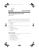
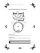
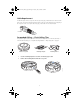
10015414-AA_AP3750_QSG.fm Page 2 Tuesday, July 25, 2006 1:59 PM 3Com AP3750 Managed Access Point Features Diameter 16.76 cm (6.6 inches) Height 4.69 cm (1.85 inches) 840-9502-0040 TM External antenna connectors Kensington security slot 802.11b/g 840-9502-0007 Unlock 802.11a RJ-45 ports Port 2 Port 1 Kensington Security Slot The access point has a slot for attachment of a Kensington security cable. The cable is not included with the access point but can be ordered separately.
10015414-AA_AP3750_QSG.fm Page 3 Tuesday, July 25, 2006 1:59 PM RJ-45 Cable Ports The access point has two RJ-45 ports. Each port provides a 10/100BASE-TX Ethernet connection to a WX switch. The connection can be direct to an WX switch or indirect through an intermediate Layer 2 or Layer 3 network. The access point receives power and data through the RJ-45 ports.
10015414-AA_AP3750_QSG.fm Page 4 Tuesday, July 25, 2006 1:59 PM WARNING: Before using a wireless device in a hazardous location, consult the local codes, national codes, and safety directors of the location for usage constraints. WARNING: Do not connect or disconnect cables or otherwise work with the access point hardware during periods of lightning activity. NOTE: The access point is intended for indoor use only. Do not install the device outdoors, unless you install it in a properly installed enclosure.
10015414-AA_AP3750_QSG.fm Page 5 Tuesday, July 25, 2006 1:59 PM 3 Connecting External Antennas The access point has connectors for attaching optional external antennas and antenna cables. The tables below list the external antenna and cable models that are certified for use with the access point.
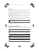
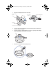
10015414-AA_AP3750_QSG.fm Page 6 Tuesday, July 25, 2006 1:59 PM Cable Requirement The Ethernet ports on the access point cannot accept a Category 5 cable that has an uneven sheath such as the one shown in the figure below. The RJ-45 connector on the cable will not seat properly in the receptacle on the access point. Use a Category 5 cable with an even sheath instead. Uneven sheath Suspended Ceiling — Flush Ceiling Tiles This procedure applies to T-bars that are 23.9 mm (15/16 inches) wide. For a 14.
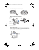
10015414-AA_AP3750_QSG.fm Page 7 Tuesday, July 25, 2006 1:59 PM 3 Attach the mounting bracket to the T-bar clamp. Universal mounting bracket Port connector opening Universal mounting bracket T-bar T-bar 840-9502-0005 Port connector opening (Viewed from above ceiling tiles, looking down.) If you are using an external antenna, insert the antenna cable into the antenna connector on the access point.
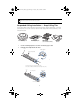
10015414-AA_AP3750_QSG.fm Page 8 Tuesday, July 25, 2006 1:59 PM CAUTION: If you plan to use an external antenna for the 802.11b/g or 802.11a radio, install the antenna at least 20 cm from the access point. Suspended Ceiling Installation — Drop Ceiling Tiles This procedure applies to T-bars that are 23.9 mm (15/16 inches), 14.2 mm (9/16 inches), or 15.9 mm (5/8 inches) wide. You can also use this procedure for flush ceilings with 14.2-mm (9/16-inch) or 15.9mm (5/8-inch) T-bars.
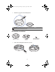
10015414-AA_AP3750_QSG.fm Page 9 Tuesday, July 25, 2006 1:59 PM Remove the mounting bracket from the access point. 4 Attach the mounting bracket to the T-bar clamp. 840-9502-0011 840-9502-0008 3 Universal mounting bracket Port connector opening T- bar Universal mounting bracket T-bar 840-9502-0012 T-bar clamps (attached to T-bar) Port connector opening (Viewed from above ceiling tiles, looking down.
015414-AA_AP3750_QSG.fm Page 10 Tuesday, July 25, 2006 1:59 PM 7 Attach the access point to the mounting bracket. Lock TM TM 840-9502-0006 T-bar CAUTION: If you plan to use an external antenna for the 802.11b/g or 802.11a radio, install the antenna at least 20 cm from the access point. Junction Box Installation TM Mobility point AP3750 access point Mounting hardware Mounting hardware 10 840-9502-0008 Remove the mounting bracket from the access point.
10015414-AA_AP3750_QSG.fm Page 11 Tuesday, July 25, 2006 1:59 PM 2 Attach the bracket to the junction box. Junction box 840-9502-0017 Port connector opening If you are using an external antenna, insert the antenna cable into the antenna connector on the access point. 4 Plug the Category 5 cable into the access point and attach the access point to the mounting bracket. TM 3 840-9502-0062 TM Lock CAUTION: If you plan to use an external antenna for the 802.11b/g or 802.
10015414-AA_AP3750_QSG.fm Page 12 Tuesday, July 25, 2006 1:59 PM Solid Wall or Ceiling Installation TM Mobility AP3750 access point point Mounting Mounting template template Mounting Mounting bracket bracket Use the mounting template to cut a hole for the Category 5 cable. 2 Remove the mounting bracket from the access point. 3 Attach the bracket to the wall or ceiling.
10015414-AA_AP3750_QSG.fm Page 13 Tuesday, July 25, 2006 1:59 PM Plug the Category 5 cable into the access point and attach the access point to the mounting bracket. Cable TM 840-9502-0016 Universal mounting bracket TM TM 840-9502-0062 5 Lock CAUTION: If you plan to use an external antenna for the 802.11b/g or 802.11a radio, install the antenna at least 20 cm from the access point.
10015414-AA_AP3750_QSG.fm Page 14 Tuesday, July 25, 2006 1:59 PM Tabletop Installation TM point Mounting Mounting bracket bracket Remove the mounting bracket from the access point. 2 Reverse the bracket and reattach it to the access point. 3 Attach the rubber feet. 4 Turn the access point over and place it on the table.
10015414-AA_AP3750_QSG.fm Page 15 Tuesday, July 25, 2006 1:59 PM 5 If you are using an external antenna, insert the antenna cable into the antenna connector on the access point. 6 Plug the Category 5 cable into the access point. CAUTION: If you plan to use an external antenna for the 802.11b/g or 802.11a radio, install the antenna at least 20 cm from the access point.
10015414-AA_AP3750_QSG.fm Page 16 Tuesday, July 25, 2006 1:59 PM 7 Checking the LED Indicators When the access point is connected to power, LEDs indicate activity as follows: Radio 1 LED Radio 2 LED Health LED LEDs Color Health Solid green Indicates • • • • Radio 1 (.11b/g) Radio 2 (.11a) 840-9502-0010 TM The access point has a valid management link with a wireless switch. The access point has booted. The access point has received a valid configuration from a wireless switch.
10015414-AA_AP3750_QSG.fm Page 17 Tuesday, July 25, 2006 1:59 PM Regulatory Information The 3Com AP3750 Managed Access Point (3CRWX375075A) must be installed and used in strict accordance with the manufacturer's instructions as described in the user documentation that comes with the product. Note: This product contains encryption. It is unlawful to export out of the U.S. without obtaining a U.S. Export License. This product does not contain any user serviceable components.
10015414-AA_AP3750_QSG.fm Page 18 Tuesday, July 25, 2006 1:59 PM MANUFACTURER'S FCC DECLARATION OF CONFORMITY 3Com Corporation 350 Campus Drive Marlborough, MA 01752-3064, USA (800) 527-8677 Date: May 6, 2005 Declares that the Product: Brand Name: 3Com Corporation Model Number: AP3750 Equipment Type: Managed Access Point Complies with Part 15 of the FCC rules.
10015414-AA_AP3750_QSG.fm Page 19 Tuesday, July 25, 2006 1:59 PM EUROPE - EU DECLARATION OF CONFORMITY This equipment may be operated in AT BE CY CZ DK EE FI FR DE GR HU IE IT LV LT LU MT NL PL PT SK SI ES SE GB IS LI NO CH BG RO TR Intended use: IEEE 802.11a/b/g radio LAN device NOTE: To ensure product operation is in compliance with local regulations, select the country in which the product is installed.
10015414-AA_AP3750_QSG.fm Page 20 Tuesday, July 25, 2006 1:59 PM Portuguese 3Com Corporation declara que este RLAN device está conforme com os requisitos essenciais e outras disposições da Directiva 1999/5/CE. Malti Hawnhekk, 3Com Corporation, jiddikjara li dan RLAN device jikkonforma mal-htigijiet essenzjali u ma provvedimenti ohrajn relevant li hemm fid-Dirrettiva 1999/5/EC.
10015414-AA_AP3750_QSG.fm Page 21 Tuesday, July 25, 2006 1:59 PM EUROPE - RESTRICTIONS FOR USE OF 5GHZ FREQUENCIES IN EUROPEAN COMMUNITY COUNTRIES Allowed Frequency Bands Allowed Channel Numbers Countries 5.15-5.25 GHz 36, 40, 44, 48 Austria 5.15-5.35 GHz 36, 40, 44, 48, 52, 56, 60, 64 Belgium, Cyprus, Czech Republic, France, Hungary, Liechtenstein, Slovakia, Switzerland 5.15-5.35 & 5.470-5.
10015414-AA_AP3750_QSG.fm Page 22 Tuesday, July 25, 2006 1:59 PM Copyright © 2006 3Com Corporation. All rights reserved. 3Com and the 3Com logo are registered trademarks of 3Com Corporation. All other company and product names may be trademarks of the respective companies with which they are associated. Part Number 10015414, Rev.