
Manual

3
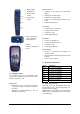
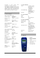
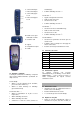
6 Digital outputs
7 Digital inputs
8 Analog outputs
A and B
9 Analog inputs
A and B
10 Recessed socket for
power supply unit
11 USB connection
12 Mount
13 Battery compartment
14 Fuse
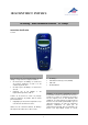
5.2 Operating controls
The operating controls of the 3B NETlog™ unit
consist of five multi-function buttons for operation
without connection to a PC.
On/Off button
• Switching the device on and off (keep the but-
ton pressed for approx. 2 seconds to switch off
the device)
• Switching the display lighting on and off
(briefly press the button)
Date/Time button ↵
• Switching on the battery and temperature
displays
• Switching on the time display
• Switching on the date display
• Selection of operating mode (manual or auto-
matic)
• Confirming the display →
Store button ↓
• Communication to data logger
• Scrolling down the menu
• Selecting Yes or No
• Confirming the display ↓
Rate button ↑
• Selection of sampling rate
• Scrolling up within the menu
• Selecting Yes or No
• Confirming the display ↑
Channel button ←
• Selection of measurement parameters for
channels A and B
• Changing between fields while setting the time
and date
• Return to previous menu
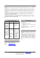
5.3 Measurement parameters
Name Significance
VdcA DC voltage on channel A
VacA AC voltage on channel A
Idc DC current on channel A
Iac AC current on channel A
VdcB DC voltage on channel B
VacB AC voltage on channel B
Bin Binary representation
5.4 Connection of sensors
Connected sensors are automatically detected by
the 3B NETlog™ device. The following status mes-
sage appears on the display:
PROBE DETECT…. Subsequently, the measurement
and the unit corresponding to the connected sen-
sor are displayed.