
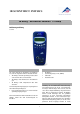
Manual

2
within a network, the teacher and students can
mutually monitor their results.
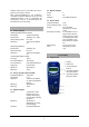
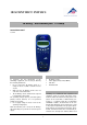
Without being connected to a computer, the
3B NETlog™ device can be used as a digital mul-
timeter for current and voltage measurements.
Combined with different sensors, the 3B NETlog™
equipment can also be used as a handheld unit
with automatic sensor recognition.
4. Technical specifications
4.1 Analog inputs
Voltage inputs (channels A and B):
Measuring equipment: 2 Differential amplifiers
Measuring range: ±200mV, ±2V, ±20V
Surge voltage protection: Max. ±40V
Connections: 4-mm safety sockets
Current input (channel A):
Measuring range: ±200mA, ±2A
Excess current protection: Max. ±2.5A
Connections: 4-mm safety sockets
Sensor inputs (channels A and B):
Sensor type: Analog
Sensor identification: Automatic
Sensor connections: 8-pin mini DIN sockets
Sampling: Continuous
Sampling rate: 50k samples/s
Resolution: 12 bit
4.2 Analog outputs (channels A and B)
Reference point (earth): Common
Measuring range: ± 5V
Connections: 4-mm safety sockets and
8-pin mini DIN sockets
Sampling rate: 10kSamples/s
Resolution: 12bit
4.3 Digital inputs
Channels: 4 (separated into 2 TTL
inputs, one of which is a
high-speed time input,
plus 2 inputs via opto-
coupler)
Sampling rate: 50k samples/s
100k samples/s (high-
speed time input)
Connection: 8-pin mini DIN socket
4.4 Digital outputs
Channels: 6
Signal: TTL
Connection: 8-pin mini DIN socket
4.5 Additional data
Computer connection: USB
Internal data memory: 128k
Display: 64 x 122 matrix for
measurements and units
Power supply: 4.5V DC/300mA or 3
batteries (AA, LR6 or
AM3); owing to their
longer battery life, use of
alkaline batteries is rec-
ommended.
Dimensions: 21cm x 8cm x 4cm
Weight: 400g (including batteries)
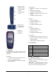
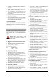
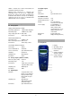
5. Description
5.1 Components
1 Display
2 Operating controls
3 Current input for
channel A
4 Voltage outputs for
channels A and B
5 Voltage inputs for
channels A and B