
User Manual


____________________________________________________________________________________
Page 116 MAXX 6T Owner’s Manual
APPENDIX F – GPIO INTERFACING
GPI Connector
General purpose control inputs (GPI) may be applied to the GPIO port, which is a DB-25-F
connector. These inputs are optically isolated from the MAXX 6T circuitry; individual floating
returns are provided. +5 volts may be sourced from pins 21 or 22, or provided from an external
source. Current limiting devices are provided within the MAXX 6T.
General purpose status outputs also appear on the GPIO connector. Open-collector outputs are
provided as status outputs, and may be used to drive an external LED or control input.
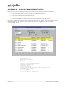
Refer to the connector pin-out table and partial schematic, following.
GPI Connector Pinout
Pin Signal Pin Signal
1 GPI 1 14 GPI 1 RTN
2 GPI
2 15 GPI
2
RTN
3 GPI
3 16 GPI
3
RTN
4 GPI
4 17 GPI
4
RTN
5 GPI
5 18 GPI
5
RTN
6 GPI
6 19 GPI
6
RTN
7 N/C 20 N/C
8,
9,
10 GND 21,
22 +5V
S
OURCE
(200
M
A
MAX
)
11 GPO
2 23 GPO
1
12 GPO
4 24 GPO
3
13 GPO
6 25 GPO
5
Warning: Incorrect wiring of GPI connector may damage GPI interface circuitry.