
Manual

____________________________________________________________________________________
MAXX 2400 Owners Manual
Page 125
APPENDIX H - AUDIO LEVEL CALIBRATION
The input gain and output gain of the analog audio circuits are factory calibrated to a +4 dBu
standard. Each circuit includes a trim pot with a range of approximately ±2.5 dB. The following
procedures may be used to calibrate these for unity gain. The audio board must be partially
removed from the chassis to perform this procedure.
1. Power off the unit. REMOVE BOTH POWER CORDS
2. Remove the Chassis top by pressing the two blue release buttons, then sliding back and up.
3. The Audio board is the left most PCI card viewed from the front of the unit. Remove the
PCI hold down screw and rock the board up, being careful not to overextend the cables
attached to it.
4. Configure the jumpers according to the ANALOG setting. See Figure 53
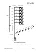
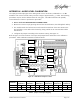
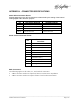
Refer to Figure 53 for the location of trim pots and jumper blocks referred to in the calibration
procedures. Table 4 Indicates mapping to audio channels.
Figure 53 - Audio Board Trimpot Location
Channel
Input
Channel 1
Input
Channel 3
Output
Channel 1
Output
Channel 2
Output
Channel 3
Output
Channel 4
Connector L R L R L R L R L R L R
Trimmer R10 R25 R40 R55 R71 R86 R101
R116
R161
R76 R191
R206
Jumpers J1 and J2 J3 and J4 J5 and J6 J7 and J8 J11 and J12 J13 and J14
Table 4 - Jumper and Trimpot mapping
C2R - R116
C2L - R101
C1R – R86
C1L – R71
C3R – R76
C3L – R161
C4R – R206
C4L – R191
IN3R – R55
IN3L – R40
IN1R – R25
IN1L – R10