
Owner manual
page 16 Instant Replay Owner’s Manual
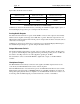
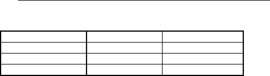
Input cables should be wired as follows:
XLR Connector Pin Balanced Connection Unbalanced Connection
PIN 1 COMMON GROUND
PIN 2 + INPUT SIGNAL
PIN 3 - INPUT No Connect
TABLE OF INPUT AND OUTPUT CONNECTIONS
Unbalanced connections should be made by connecting the unbalanced signal output to pin 2 of
the Instant Replay and ground to pin 1, with pin 3 left unconnected.
Analog Audio Outputs
The main ANALOG OUTPUTS are a pair of male XLR-3 connectors. The output is electronically
balanced, and is capable of driving loads of 600 ohms or greater. Full scale output level is +25
dBu with the OUTPUT ATTENUATOR in the 0 position. Output cables should be wired the same as
shown above for the inputs.
Unbalanced connections are achieved by connecting pin 2 of the Instant Replay XLR Output to
the unbalanced input and pin 1 to ground, with pin 3 left unconnected.
Output Attenuator Switch
The OUTPUT ATTENUATOR switch is located on the rear panel. Set this switch to the in position
for operation of Instant Replay with equipment having a nominal operating level of +4 dBu. Set
the switch to the out position for use with equipment operating at -10 dBm.
The switch has no effect on the LEVEL METERS, digital audio outputs, or the HEADPHONE
OUTPUT.
Headphone Output
The HEADPHONE OUTPUT always carries the same signal as the Main outputs, but its level is
controlled by the HEADPHONES LEVEL control on the front panel.
When the PREVIEW button is activated in Stop mode, the HEADPHONE OUTPUT is active and the
Main Outputs (ANALOG OUTPUT, AES/EBU DIGITAL OUT and IEC-958 II OUT) are turned off
during subsequent playback. It may be helpful to use the HEADPHONE OUTPUT for control room
monitoring, while the Main Outputs provide the main feed to a mixer or transmitter.