
- LG Software Innovations Coffeemaker User Manual
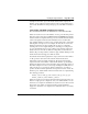
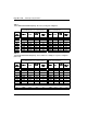
Table Of Contents
- Title Page
- Revision history
- Contents
- About this guide
- Description
- System requirements
- List of ITG ISDN components
- Ordering rules and guidelines
- ITG ISL Trunk card description
- ITG ISL Trunk card physical description
- ISDN Signaling Link
- Dialing plans
- Quality of Service
- Fallback to alternate facilities
- Type of Service
- Fax support
- Remote Access
- Per-call statistics support using RADIUS Client
- SNMP MIB
- Codec profiles
- Security passwords
- ITG Engineering Guidelines
- Introduction
- Network engineering guidelines overview
- ITG traffic engineering
- Configuration of Meridian 1 routes and network translation
- Assess WAN link resources
- QoS Evaluation Process Overview
- Set QoS
- Measure intranet QoS
- Implement QoS in IP networks
- ITG Trunk DSP profile settings
- Post-installation network measurements
- Estimate QoS level
- ITG MAT PC management configuration
- Install and configure ITG ISL Trunk node
- Before you begin
- Installation Procedure Summary
- Create the ITG Trunk Installation Summary Sheet
- Install and cable ITG trunk cards
- Install NTCW84JA Large System I/O Panel 50-Pin filter adapter
- Install NTMF94EA and NTCW84KA cables
- D-channel cabling for the NT0961AA 24-Port ITG Trunk card
- Set NT6D80 MSDL switches
- Install filter and NTND26 cable (for MSDL and DCHIP cards in same Large System equipment row)
- Install filter and NTND26 cable (for MSDL and DCHIP cards in different Large System equipment rows)
- Configure ITG Trunk data on the Meridian 1
- Configure dialing plans within the corporate network
- Configure ITG Trunk data on MAT
- Transmit ITG trunk card configuration data from MAT to the ITG trunk cards
- Set date and time for the ITG ISL Trunk node
- Change the default ITG shell password to maintain access security
- Change default ESN5 prefix for non-ESN5 IP telephony gateways
- Check card software
- Configure MAT Alarm Management to receive SNMP traps from ITG ISL Trunk cards
- Make test calls to the remote ITG nodes
- Upgrade an ITG Trunk 1.0 node to support ISDN signaling trunks
- Upgrade procedure summary
- Before you begin
- Install the DCHIP hardware upgrade kit
- Upgrade the 8-port ITG basic trunk software to ITG ISL trunk software
- Remove ITG 1.0 configuration data from Meridian 1
- Configure the Meridian 1 ITG ISL Trunk data: upgrade considerations
- Verify ROM-BIOS version
- Upgrade Troubleshooting
- OA&M using MAT applications
- OA&M using the ITG shell CLI and overlays
- Maintenance
- Appendix A: Calbe description and NT8D81BA cable replacement
- NTMF94EA E - LAN, T - LAN and Serial Port cable
- NTCW84KA E-LAN, T-LAN, DCH & Serial cable
- NTAG81CA Faceplate Maintenance cable
- NTAG81BA Maintenance Extender cable
- NTCW84EA DCH PC Card Pigtail cable
- NTMF04BA MSDL extension cable
- NTCW84LA and NTCW84MA upgrade cables
- Prevent ground loops on connection to external customer LAN equipment
- Replace cable NT8D81BA with NT8D81AA
- Tools list
- NT8D81BA cable removal procedures
- Appendix B: Environmental and electrical regulatory data
- Appendix C: Subnet mask conversion from CIDR to dotted decimal format
- Appendix D: Configure a Netgear RM356 modem router for remote access
- Index
- Back

Page 84 of
378
ITG Engineering Guidelines
553-3001-202 Standard 1.00 April 2000
5 Calculate average bandwidth use on T-LAN
For voice:
720/36*30.7 =614 kbit/s
Refer to Table 5 (silence suppression enabled), data output for G.729
Annex AB and 30 ms payload is 30.7 kbit/s.
For fax:
84/36*46.1 =108 kbit/s
Total bandwidth = 614 + 108 = 722 kbit/s
6 Adjust requirement for traffic peaking
Peak hour bandwidth requirement = 722*1.3 = 939 kbit/s
This is the spare bandwidth a T-LAN should have to handle the VoIP
and fax traffic. It is recommended that the T-LAN handle ITG traffic
exclusively.
Note that this example is based on the G.729 Annex AB codec with 30 ms
payload size and silence suppression enabled. For relations of user selectable
parameters (e.g., payload size, codec type, packet size and QoS), refer to “Set
QoS” on page 108.
General LAN and WAN engineering considerations
The T-LAN traffic capacity does not limit ITG network engineering. Refer to
“Set up a system with separate subnets for voice and management” on
page 130 and “Single subnet option for voice and management” on page 131
Refer to standard Ethernet engineering tables for passive 10/100BaseT
repeater hubs. Refer to manufacturer’s specifications for intelligent
10/100BaseT layer switches.
A passive 10/100BaseT Ethernet hub is a half-duplex data transport
mechanism. Both “talk” and “listen” traffic use a part of the nominal
10 Mbit/s capacity. The customer must then set up the passive 10/100BaseT
Ethernet hub so that T-LAN voice traffic does not exceed 3MB/second on a
10/100BaseT Ethernet. A 10/100BaseT Ethernet switch port can operate in
either half-duplex or full-duplex mode, but ITG Ethernet interfaces operate
only in half-duplex mode. A switched Ethernet hub can reach throughput of
10MB/second. See your manufacturer’s specifications for more information.