
- LG Software Innovations Coffeemaker User Manual

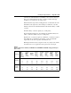
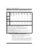

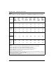
Table Of Contents
- Title Page
- Revision history
- Contents
- About this guide
- Description
- System requirements
- List of ITG ISDN components
- Ordering rules and guidelines
- ITG ISL Trunk card description
- ITG ISL Trunk card physical description
- ISDN Signaling Link
- Dialing plans
- Quality of Service
- Fallback to alternate facilities
- Type of Service
- Fax support
- Remote Access
- Per-call statistics support using RADIUS Client
- SNMP MIB
- Codec profiles
- Security passwords
- ITG Engineering Guidelines
- Introduction
- Network engineering guidelines overview
- ITG traffic engineering
- Configuration of Meridian 1 routes and network translation
- Assess WAN link resources
- QoS Evaluation Process Overview
- Set QoS
- Measure intranet QoS
- Implement QoS in IP networks
- ITG Trunk DSP profile settings
- Post-installation network measurements
- Estimate QoS level
- ITG MAT PC management configuration
- Install and configure ITG ISL Trunk node
- Before you begin
- Installation Procedure Summary
- Create the ITG Trunk Installation Summary Sheet
- Install and cable ITG trunk cards
- Install NTCW84JA Large System I/O Panel 50-Pin filter adapter
- Install NTMF94EA and NTCW84KA cables
- D-channel cabling for the NT0961AA 24-Port ITG Trunk card
- Set NT6D80 MSDL switches
- Install filter and NTND26 cable (for MSDL and DCHIP cards in same Large System equipment row)
- Install filter and NTND26 cable (for MSDL and DCHIP cards in different Large System equipment rows)
- Configure ITG Trunk data on the Meridian 1
- Configure dialing plans within the corporate network
- Configure ITG Trunk data on MAT
- Transmit ITG trunk card configuration data from MAT to the ITG trunk cards
- Set date and time for the ITG ISL Trunk node
- Change the default ITG shell password to maintain access security
- Change default ESN5 prefix for non-ESN5 IP telephony gateways
- Check card software
- Configure MAT Alarm Management to receive SNMP traps from ITG ISL Trunk cards
- Make test calls to the remote ITG nodes
- Upgrade an ITG Trunk 1.0 node to support ISDN signaling trunks
- Upgrade procedure summary
- Before you begin
- Install the DCHIP hardware upgrade kit
- Upgrade the 8-port ITG basic trunk software to ITG ISL trunk software
- Remove ITG 1.0 configuration data from Meridian 1
- Configure the Meridian 1 ITG ISL Trunk data: upgrade considerations
- Verify ROM-BIOS version
- Upgrade Troubleshooting
- OA&M using MAT applications
- OA&M using the ITG shell CLI and overlays
- Maintenance
- Appendix A: Calbe description and NT8D81BA cable replacement
- NTMF94EA E - LAN, T - LAN and Serial Port cable
- NTCW84KA E-LAN, T-LAN, DCH & Serial cable
- NTAG81CA Faceplate Maintenance cable
- NTAG81BA Maintenance Extender cable
- NTCW84EA DCH PC Card Pigtail cable
- NTMF04BA MSDL extension cable
- NTCW84LA and NTCW84MA upgrade cables
- Prevent ground loops on connection to external customer LAN equipment
- Replace cable NT8D81BA with NT8D81AA
- Tools list
- NT8D81BA cable removal procedures
- Appendix B: Environmental and electrical regulatory data
- Appendix C: Subnet mask conversion from CIDR to dotted decimal format
- Appendix D: Configure a Netgear RM356 modem router for remote access
- Index
- Back

Page 76 of
378
ITG Engineering Guidelines
553-3001-202 Standard 1.00 April 2000
ITG traffic engineering
To design a network is to size the network so that it can accept some
calculated amount of traffic. The purpose of the ITG network is to deliver
voice traffic meeting the QoS objectives. Since traffic determines network
design, the design process needs to start with the process of obtaining offered
ITG traffic forecast. The traffic forecast will drive:
• WAN requirements
• ITG hardware requirements
• T-LAN requirements
Use
of Ethernet and WAN bandwidth
Table 5 on page 77 lists the Ethernet and WAN bandwidth use of ITG ports
with different codecs with silence suppression enabled, and Table 6 on
page 80 lists the use with silence suppression disabled. One port is a channel
fully loaded to 36 CCS, where one CCS (Centi-Call-Second) is a
channel/circuit being occupied 100 seconds. 36 CCS is a circuit occupied for
a full hour. To calculate the bandwidth requirement of a route, the total route
traffic should be divided by 36 CCS and multiplied by the bandwidth use to
get the data rate requirement of that route. All traffic data must be based on
the busy hour of the busy day.
Note that to calculate resource requirements (ITG ports and T-LAN/WAN
bandwidth), traffic parcels are summarized in different ways:
1 Add all sources of traffic for the ITG network, e.g., voice, fax sent, fax
received, together to calculate ITG port and T-LAN requirements.
2 For data rate requirement at each route, the calculation is based on each
destination pair.
3 For fax traffic on a WAN, only the larger of either the fax-sent or
fax-received traffic is to be accounted for.
The engineering procedures for T-LAN and WAN are different. The
following calculation procedure is for T-LAN (the modification required for
WAN engineering is included in these procedures).