
- LG Software Innovations Coffeemaker User Manual
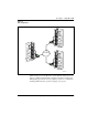
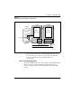
Table Of Contents
- Title Page
- Revision history
- Contents
- About this guide
- Description
- System requirements
- List of ITG ISDN components
- Ordering rules and guidelines
- ITG ISL Trunk card description
- ITG ISL Trunk card physical description
- ISDN Signaling Link
- Dialing plans
- Quality of Service
- Fallback to alternate facilities
- Type of Service
- Fax support
- Remote Access
- Per-call statistics support using RADIUS Client
- SNMP MIB
- Codec profiles
- Security passwords
- ITG Engineering Guidelines
- Introduction
- Network engineering guidelines overview
- ITG traffic engineering
- Configuration of Meridian 1 routes and network translation
- Assess WAN link resources
- QoS Evaluation Process Overview
- Set QoS
- Measure intranet QoS
- Implement QoS in IP networks
- ITG Trunk DSP profile settings
- Post-installation network measurements
- Estimate QoS level
- ITG MAT PC management configuration
- Install and configure ITG ISL Trunk node
- Before you begin
- Installation Procedure Summary
- Create the ITG Trunk Installation Summary Sheet
- Install and cable ITG trunk cards
- Install NTCW84JA Large System I/O Panel 50-Pin filter adapter
- Install NTMF94EA and NTCW84KA cables
- D-channel cabling for the NT0961AA 24-Port ITG Trunk card
- Set NT6D80 MSDL switches
- Install filter and NTND26 cable (for MSDL and DCHIP cards in same Large System equipment row)
- Install filter and NTND26 cable (for MSDL and DCHIP cards in different Large System equipment rows)
- Configure ITG Trunk data on the Meridian 1
- Configure dialing plans within the corporate network
- Configure ITG Trunk data on MAT
- Transmit ITG trunk card configuration data from MAT to the ITG trunk cards
- Set date and time for the ITG ISL Trunk node
- Change the default ITG shell password to maintain access security
- Change default ESN5 prefix for non-ESN5 IP telephony gateways
- Check card software
- Configure MAT Alarm Management to receive SNMP traps from ITG ISL Trunk cards
- Make test calls to the remote ITG nodes
- Upgrade an ITG Trunk 1.0 node to support ISDN signaling trunks
- Upgrade procedure summary
- Before you begin
- Install the DCHIP hardware upgrade kit
- Upgrade the 8-port ITG basic trunk software to ITG ISL trunk software
- Remove ITG 1.0 configuration data from Meridian 1
- Configure the Meridian 1 ITG ISL Trunk data: upgrade considerations
- Verify ROM-BIOS version
- Upgrade Troubleshooting
- OA&M using MAT applications
- OA&M using the ITG shell CLI and overlays
- Maintenance
- Appendix A: Calbe description and NT8D81BA cable replacement
- NTMF94EA E - LAN, T - LAN and Serial Port cable
- NTCW84KA E-LAN, T-LAN, DCH & Serial cable
- NTAG81CA Faceplate Maintenance cable
- NTAG81BA Maintenance Extender cable
- NTCW84EA DCH PC Card Pigtail cable
- NTMF04BA MSDL extension cable
- NTCW84LA and NTCW84MA upgrade cables
- Prevent ground loops on connection to external customer LAN equipment
- Replace cable NT8D81BA with NT8D81AA
- Tools list
- NT8D81BA cable removal procedures
- Appendix B: Environmental and electrical regulatory data
- Appendix C: Subnet mask conversion from CIDR to dotted decimal format
- Appendix D: Configure a Netgear RM356 modem router for remote access
- Index
- Back

Description Page 49 of
378
ITG Trunk 2.0 ISDN Signaling Link (ISL) Description, Installation and Operation
Dialing plans
Dialing plan configuration allows customers to set up routing tables to route
calls to the appropriate destination, based on dialed digits. The dialing plan is
configured through the Electronic Switched Network (ESN) feature, using
overlays in the Meridian 1 or MAT. With ESN configuration, the Meridian 1
can route outgoing calls to the ITG ISL Trunk card. Address translation
allows the ITG ISL Trunk card call processing to translate the called party
number to the IP address of the terminating ITG node, and to deliver calls to
the destination through the IP network.
The Meridian 1 ITG ISL Trunk card supports the following dialing plans:
• North American dialing plan
• Flexible Numbering Plan
Customer-defined Basic Automatic Route Selection (BARS) and Network
Alternate Route Selection (NARS) Access Codes are used to access the
dialing plans.
The ITG Trunk dialing plan supports a single Meridian 1 customer per ITG
node and multiple ITG nodes per Meridian 1. A customer may have multiple
nodes in a Meridian 1, but each node can only support the dialing plan of a
single customer. Multiple Meridian 1 customers will require multiple nodes
per Meridian 1.
Multi-node configuration
The following example explains a possible configuration between two
Meridian 1 switches to achieve both resiliency into the IP network and load
balancing.
Meridian 1 switch A has two ITG nodes, A1 and A2, for the destination NPA
613. A Route List Block (RLB) is created, in order to have two route entries
(one for each ITG node). If the trunks of node A1 are all in use or node A1 is
down, call traffic is routed to node A2. This provides resiliency by preventing
failure of a single ITG node (for example, DCH failure or Leader subnet fails)
from completely eliminating VoIP service for a Meridian 1 system.
It is desirable to distribute calls to multiple nodes at a remote destination
Meridian 1. The configuration of multiple dialing plan entries at the local ITG
node allows routing based on the dialed digits.