
- LG Software Innovations Coffeemaker User Manual
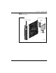
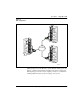
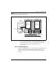
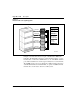
Table Of Contents
- Title Page
- Revision history
- Contents
- About this guide
- Description
- System requirements
- List of ITG ISDN components
- Ordering rules and guidelines
- ITG ISL Trunk card description
- ITG ISL Trunk card physical description
- ISDN Signaling Link
- Dialing plans
- Quality of Service
- Fallback to alternate facilities
- Type of Service
- Fax support
- Remote Access
- Per-call statistics support using RADIUS Client
- SNMP MIB
- Codec profiles
- Security passwords
- ITG Engineering Guidelines
- Introduction
- Network engineering guidelines overview
- ITG traffic engineering
- Configuration of Meridian 1 routes and network translation
- Assess WAN link resources
- QoS Evaluation Process Overview
- Set QoS
- Measure intranet QoS
- Implement QoS in IP networks
- ITG Trunk DSP profile settings
- Post-installation network measurements
- Estimate QoS level
- ITG MAT PC management configuration
- Install and configure ITG ISL Trunk node
- Before you begin
- Installation Procedure Summary
- Create the ITG Trunk Installation Summary Sheet
- Install and cable ITG trunk cards
- Install NTCW84JA Large System I/O Panel 50-Pin filter adapter
- Install NTMF94EA and NTCW84KA cables
- D-channel cabling for the NT0961AA 24-Port ITG Trunk card
- Set NT6D80 MSDL switches
- Install filter and NTND26 cable (for MSDL and DCHIP cards in same Large System equipment row)
- Install filter and NTND26 cable (for MSDL and DCHIP cards in different Large System equipment rows)
- Configure ITG Trunk data on the Meridian 1
- Configure dialing plans within the corporate network
- Configure ITG Trunk data on MAT
- Transmit ITG trunk card configuration data from MAT to the ITG trunk cards
- Set date and time for the ITG ISL Trunk node
- Change the default ITG shell password to maintain access security
- Change default ESN5 prefix for non-ESN5 IP telephony gateways
- Check card software
- Configure MAT Alarm Management to receive SNMP traps from ITG ISL Trunk cards
- Make test calls to the remote ITG nodes
- Upgrade an ITG Trunk 1.0 node to support ISDN signaling trunks
- Upgrade procedure summary
- Before you begin
- Install the DCHIP hardware upgrade kit
- Upgrade the 8-port ITG basic trunk software to ITG ISL trunk software
- Remove ITG 1.0 configuration data from Meridian 1
- Configure the Meridian 1 ITG ISL Trunk data: upgrade considerations
- Verify ROM-BIOS version
- Upgrade Troubleshooting
- OA&M using MAT applications
- OA&M using the ITG shell CLI and overlays
- Maintenance
- Appendix A: Calbe description and NT8D81BA cable replacement
- NTMF94EA E - LAN, T - LAN and Serial Port cable
- NTCW84KA E-LAN, T-LAN, DCH & Serial cable
- NTAG81CA Faceplate Maintenance cable
- NTAG81BA Maintenance Extender cable
- NTCW84EA DCH PC Card Pigtail cable
- NTMF04BA MSDL extension cable
- NTCW84LA and NTCW84MA upgrade cables
- Prevent ground loops on connection to external customer LAN equipment
- Replace cable NT8D81BA with NT8D81AA
- Tools list
- NT8D81BA cable removal procedures
- Appendix B: Environmental and electrical regulatory data
- Appendix C: Subnet mask conversion from CIDR to dotted decimal format
- Appendix D: Configure a Netgear RM356 modem router for remote access
- Index
- Back

Description Page 41 of
378
ITG Trunk 2.0 ISDN Signaling Link (ISL) Description, Installation and Operation
Reset switch
A reset switch on the faceplate allows an operator to manually reset the card
without having to cycle power to the card. This switch is normally used
following a software upgrade to the card or, alternatively, to clear a fault
condition.
PC Card socket
There are two PC Card sockets. The faceplate socket accepts either a Type I,
II, or Type III PC Card and is designated ATA device A:. The internal socket
is reserved for the NTWE07AA C7LIU DCH PC Card on the DCHIP.
Maintenance displa
y
This is a four character, LED-based dot matrix display. It shows the card boot
sequence and is labeled with the card role as follows:
• LDR = Active Leader
• BLDR = Backup Leader
• FLR = Follower
RS-232 maintenance port
The ITG ISL Trunk card has a DIN-8 serial maintenance port connection on
the faceplate and an alternative connection to the same serial port on the I/O
backplane. Do not connect two maintenance terminals to both the faceplate
and I/O panel serial maintenance port connections at the same time.
Voice Ethernet port (T-LAN)
The faceplate Ethernet connector is a 9-pin, sub-miniature D-type connector.
The voice Ethernet port on the daughterboard is identified as “lnPci1” in the
ITG shell.
WARNING
Do not connect a T-LAN cable to the Faceplate 9-pin Voice port
connector (NWK). You must connect the T-LAN cable to the I/O
cable.