
- LG Software Innovations Coffeemaker User Manual
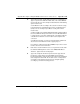
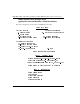
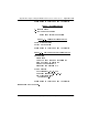
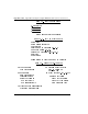
Table Of Contents
- Title Page
- Revision history
- Contents
- About this guide
- Description
- System requirements
- List of ITG ISDN components
- Ordering rules and guidelines
- ITG ISL Trunk card description
- ITG ISL Trunk card physical description
- ISDN Signaling Link
- Dialing plans
- Quality of Service
- Fallback to alternate facilities
- Type of Service
- Fax support
- Remote Access
- Per-call statistics support using RADIUS Client
- SNMP MIB
- Codec profiles
- Security passwords
- ITG Engineering Guidelines
- Introduction
- Network engineering guidelines overview
- ITG traffic engineering
- Configuration of Meridian 1 routes and network translation
- Assess WAN link resources
- QoS Evaluation Process Overview
- Set QoS
- Measure intranet QoS
- Implement QoS in IP networks
- ITG Trunk DSP profile settings
- Post-installation network measurements
- Estimate QoS level
- ITG MAT PC management configuration
- Install and configure ITG ISL Trunk node
- Before you begin
- Installation Procedure Summary
- Create the ITG Trunk Installation Summary Sheet
- Install and cable ITG trunk cards
- Install NTCW84JA Large System I/O Panel 50-Pin filter adapter
- Install NTMF94EA and NTCW84KA cables
- D-channel cabling for the NT0961AA 24-Port ITG Trunk card
- Set NT6D80 MSDL switches
- Install filter and NTND26 cable (for MSDL and DCHIP cards in same Large System equipment row)
- Install filter and NTND26 cable (for MSDL and DCHIP cards in different Large System equipment rows)
- Configure ITG Trunk data on the Meridian 1
- Configure dialing plans within the corporate network
- Configure ITG Trunk data on MAT
- Transmit ITG trunk card configuration data from MAT to the ITG trunk cards
- Set date and time for the ITG ISL Trunk node
- Change the default ITG shell password to maintain access security
- Change default ESN5 prefix for non-ESN5 IP telephony gateways
- Check card software
- Configure MAT Alarm Management to receive SNMP traps from ITG ISL Trunk cards
- Make test calls to the remote ITG nodes
- Upgrade an ITG Trunk 1.0 node to support ISDN signaling trunks
- Upgrade procedure summary
- Before you begin
- Install the DCHIP hardware upgrade kit
- Upgrade the 8-port ITG basic trunk software to ITG ISL trunk software
- Remove ITG 1.0 configuration data from Meridian 1
- Configure the Meridian 1 ITG ISL Trunk data: upgrade considerations
- Verify ROM-BIOS version
- Upgrade Troubleshooting
- OA&M using MAT applications
- OA&M using the ITG shell CLI and overlays
- Maintenance
- Appendix A: Calbe description and NT8D81BA cable replacement
- NTMF94EA E - LAN, T - LAN and Serial Port cable
- NTCW84KA E-LAN, T-LAN, DCH & Serial cable
- NTAG81CA Faceplate Maintenance cable
- NTAG81BA Maintenance Extender cable
- NTCW84EA DCH PC Card Pigtail cable
- NTMF04BA MSDL extension cable
- NTCW84LA and NTCW84MA upgrade cables
- Prevent ground loops on connection to external customer LAN equipment
- Replace cable NT8D81BA with NT8D81AA
- Tools list
- NT8D81BA cable removal procedures
- Appendix B: Environmental and electrical regulatory data
- Appendix C: Subnet mask conversion from CIDR to dotted decimal format
- Appendix D: Configure a Netgear RM356 modem router for remote access
- Index
- Back

Page 362 of
378
Appendix D: Configure a Netgear RM356 modem router for remote access
553-3001-202 Standard 1.00 April 2000
4 Type in the system name(19 characters, no spaces), location, and
contact person's name for the Meridian 1 site. Use the up and down
arrow keys to move the cursor to the prompt "Press ENTER to Confirm
or ESC to Cancel:"at the bottom of the menu. Press Enter to confirm
and save data to ROM.
5 Enter menu selection number 2 under the "Getting Started" section.
"Menu 2: Modem" is displayed.
6 Type in modem name. Set "Active=Yes". Use arrow keys to navigate
and space bar to toggle values. Set "Direction=Incoming". Type in the
modem router's telephone number for reference. Press Enter to
confirm and save data to ROM.
7 Enter menu selection number 3, "Ethernet Setup", under the "Getting
started" section.
"Menu 3: Ethernet Setup" sub-menu is displayed.
8 Enter menu selection 2, "TCP/IP and DHCP Setup".
"Menu 3.2 - TCP/IP and DHCP Ethernet Setup" is displayed.
9 Use the space bar to toggle "DHCP=None".
10 Under "TCP/IP Setup", type in the IP address and the IP subnet mask
for the modem router's Ethernet interface on the E-LAN.
11 Toggle "RIP Direction=None". Press Enter to confirm and save data to
ROM, then press Esc to return from the sub-menu to the main menu.
12 Enter menu selection number 12, "Static Routing Setup", under the
"Advanced Applications" section.
"Menu 12 - Static Route Setup" sub-menu is displayed.
Note 1:
If firewall security is properly configured in the customer's
Management GW router, and if the modem router is permitted access
over the C-LAN to other ITG nodes on remote E-LANs, define a default
network route pointing to the Management GW IP address on the local
E-LAN. Alternatively, define up to four different static network routes or
host routes in the modem router to limit routing access from the
modem router to the C-LAN.
Note 2:
To prevent access from the modem router to the C-LAN via
the Management GW router on the E-LAN, disable RIP by setting "RIP
Direction=None", and remove all static routes or disable a particular
static route by setting "Active=No".