
- LG Software Innovations Coffeemaker User Manual
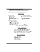
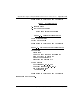
Table Of Contents
- Title Page
- Revision history
- Contents
- About this guide
- Description
- System requirements
- List of ITG ISDN components
- Ordering rules and guidelines
- ITG ISL Trunk card description
- ITG ISL Trunk card physical description
- ISDN Signaling Link
- Dialing plans
- Quality of Service
- Fallback to alternate facilities
- Type of Service
- Fax support
- Remote Access
- Per-call statistics support using RADIUS Client
- SNMP MIB
- Codec profiles
- Security passwords
- ITG Engineering Guidelines
- Introduction
- Network engineering guidelines overview
- ITG traffic engineering
- Configuration of Meridian 1 routes and network translation
- Assess WAN link resources
- QoS Evaluation Process Overview
- Set QoS
- Measure intranet QoS
- Implement QoS in IP networks
- ITG Trunk DSP profile settings
- Post-installation network measurements
- Estimate QoS level
- ITG MAT PC management configuration
- Install and configure ITG ISL Trunk node
- Before you begin
- Installation Procedure Summary
- Create the ITG Trunk Installation Summary Sheet
- Install and cable ITG trunk cards
- Install NTCW84JA Large System I/O Panel 50-Pin filter adapter
- Install NTMF94EA and NTCW84KA cables
- D-channel cabling for the NT0961AA 24-Port ITG Trunk card
- Set NT6D80 MSDL switches
- Install filter and NTND26 cable (for MSDL and DCHIP cards in same Large System equipment row)
- Install filter and NTND26 cable (for MSDL and DCHIP cards in different Large System equipment rows)
- Configure ITG Trunk data on the Meridian 1
- Configure dialing plans within the corporate network
- Configure ITG Trunk data on MAT
- Transmit ITG trunk card configuration data from MAT to the ITG trunk cards
- Set date and time for the ITG ISL Trunk node
- Change the default ITG shell password to maintain access security
- Change default ESN5 prefix for non-ESN5 IP telephony gateways
- Check card software
- Configure MAT Alarm Management to receive SNMP traps from ITG ISL Trunk cards
- Make test calls to the remote ITG nodes
- Upgrade an ITG Trunk 1.0 node to support ISDN signaling trunks
- Upgrade procedure summary
- Before you begin
- Install the DCHIP hardware upgrade kit
- Upgrade the 8-port ITG basic trunk software to ITG ISL trunk software
- Remove ITG 1.0 configuration data from Meridian 1
- Configure the Meridian 1 ITG ISL Trunk data: upgrade considerations
- Verify ROM-BIOS version
- Upgrade Troubleshooting
- OA&M using MAT applications
- OA&M using the ITG shell CLI and overlays
- Maintenance
- Appendix A: Calbe description and NT8D81BA cable replacement
- NTMF94EA E - LAN, T - LAN and Serial Port cable
- NTCW84KA E-LAN, T-LAN, DCH & Serial cable
- NTAG81CA Faceplate Maintenance cable
- NTAG81BA Maintenance Extender cable
- NTCW84EA DCH PC Card Pigtail cable
- NTMF04BA MSDL extension cable
- NTCW84LA and NTCW84MA upgrade cables
- Prevent ground loops on connection to external customer LAN equipment
- Replace cable NT8D81BA with NT8D81AA
- Tools list
- NT8D81BA cable removal procedures
- Appendix B: Environmental and electrical regulatory data
- Appendix C: Subnet mask conversion from CIDR to dotted decimal format
- Appendix D: Configure a Netgear RM356 modem router for remote access
- Index
- Back

Appendix D: Configure a Netgear RM356 modem router for remote access Page 361 of
378
ITG Trunk 2.0 ISDN Signaling Link (ISL) Description, Installation and Operation
Configure the MAT ITG PC to communicate with a
remote Meridian 1 site via modem router
If your version of MAT does not support the modem router communication
profile for Meridian 1 system types, you may work around the limitation by
configuring a Dial-up Networking (DUN) session under MS Windows to
connect to the modem router at a particular Meridian 1 site.
In the MAT Navigator, you must configure the Meridian 1 system
communication profile as "Ethernet." You must establish the Dial-up
Networking session from MS Windows before attempting to connect to the
Meridian 1 system from the MAT Navigator. ITG nodes on the same E-LAN
will also be accessible over the same Dial-up Networking connection to the
modem router.
Configure the RM356 modem router by the manager menu
Configuring the RM356 modem router by the manager menu can be
completed from a terminal or PC connected to the local RS232 manager port
on the rear of the modem router. Alternatively the manager menu can be
accessed by Telnet after the IP addressing and routing have been set up
initially from the local manager port.
Note: The arrow keys navigate in the RM356 manager menu. The
spacebar key toggles pre-defined configuration values for a field. The
Enter key saves data changes to ROM and exits the current menu. The
Esc key exits the current menu without saving changes. Enter menu
selection number when prompted to display a sub-menu, configuration
form, or command prompts.
1 Press the Enter key.
The 'Enter Password:' prompt is displayed for 10 seconds.
2 Enter the default RM356 manager password: 1234
The "RM356 Main Menu" is displayed.
3 Enter menu selection number 1 to access "General Setup" under the
"Getting Started" section of the "RM356 Main Menu."
"Menu 1 General Setup" is displayed.