
- LG Software Innovations Coffeemaker User Manual
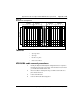
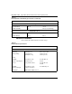
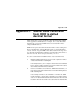
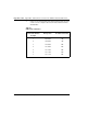
Table Of Contents
- Title Page
- Revision history
- Contents
- About this guide
- Description
- System requirements
- List of ITG ISDN components
- Ordering rules and guidelines
- ITG ISL Trunk card description
- ITG ISL Trunk card physical description
- ISDN Signaling Link
- Dialing plans
- Quality of Service
- Fallback to alternate facilities
- Type of Service
- Fax support
- Remote Access
- Per-call statistics support using RADIUS Client
- SNMP MIB
- Codec profiles
- Security passwords
- ITG Engineering Guidelines
- Introduction
- Network engineering guidelines overview
- ITG traffic engineering
- Configuration of Meridian 1 routes and network translation
- Assess WAN link resources
- QoS Evaluation Process Overview
- Set QoS
- Measure intranet QoS
- Implement QoS in IP networks
- ITG Trunk DSP profile settings
- Post-installation network measurements
- Estimate QoS level
- ITG MAT PC management configuration
- Install and configure ITG ISL Trunk node
- Before you begin
- Installation Procedure Summary
- Create the ITG Trunk Installation Summary Sheet
- Install and cable ITG trunk cards
- Install NTCW84JA Large System I/O Panel 50-Pin filter adapter
- Install NTMF94EA and NTCW84KA cables
- D-channel cabling for the NT0961AA 24-Port ITG Trunk card
- Set NT6D80 MSDL switches
- Install filter and NTND26 cable (for MSDL and DCHIP cards in same Large System equipment row)
- Install filter and NTND26 cable (for MSDL and DCHIP cards in different Large System equipment rows)
- Configure ITG Trunk data on the Meridian 1
- Configure dialing plans within the corporate network
- Configure ITG Trunk data on MAT
- Transmit ITG trunk card configuration data from MAT to the ITG trunk cards
- Set date and time for the ITG ISL Trunk node
- Change the default ITG shell password to maintain access security
- Change default ESN5 prefix for non-ESN5 IP telephony gateways
- Check card software
- Configure MAT Alarm Management to receive SNMP traps from ITG ISL Trunk cards
- Make test calls to the remote ITG nodes
- Upgrade an ITG Trunk 1.0 node to support ISDN signaling trunks
- Upgrade procedure summary
- Before you begin
- Install the DCHIP hardware upgrade kit
- Upgrade the 8-port ITG basic trunk software to ITG ISL trunk software
- Remove ITG 1.0 configuration data from Meridian 1
- Configure the Meridian 1 ITG ISL Trunk data: upgrade considerations
- Verify ROM-BIOS version
- Upgrade Troubleshooting
- OA&M using MAT applications
- OA&M using the ITG shell CLI and overlays
- Maintenance
- Appendix A: Calbe description and NT8D81BA cable replacement
- NTMF94EA E - LAN, T - LAN and Serial Port cable
- NTCW84KA E-LAN, T-LAN, DCH & Serial cable
- NTAG81CA Faceplate Maintenance cable
- NTAG81BA Maintenance Extender cable
- NTCW84EA DCH PC Card Pigtail cable
- NTMF04BA MSDL extension cable
- NTCW84LA and NTCW84MA upgrade cables
- Prevent ground loops on connection to external customer LAN equipment
- Replace cable NT8D81BA with NT8D81AA
- Tools list
- NT8D81BA cable removal procedures
- Appendix B: Environmental and electrical regulatory data
- Appendix C: Subnet mask conversion from CIDR to dotted decimal format
- Appendix D: Configure a Netgear RM356 modem router for remote access
- Index
- Back

Page 357 of
378
ITG Trunk 2.0 ISDN Signaling Link (ISL) Description, Installation and Operation
358
Appendix C: Subnet mask conversion
from CIDR to dotted
decimal format
Subnet masks can be expressed in Classless Inter Domain Routing (CIDR)
format, appended to the IP address (for example, 10.1.1.1/20). The subnet
mask must be converted from CIDR format to dotted decimal format to
configure ITG IP addresses.
CIDR format expresses the subnet mask as the number of bits counting from
the most significant bit of the first IP address field. A complete IP address
consists of 32 bits. A typical CIDR format subnet mask is in the range from
/9 to /30. Each decimal number field in the dotted decimal format can have a
value from 0 to 255, where 255 represents binary 1111 1111.
To convert a subnet mask from CIDR format to dotted decimal format:
1 Divide the CIDR format value by 8. The result is equal to the number
of dotted decimal fields containing 255.
In the example above, (10.1.1.1/20), the subnet mask is /20. 20 divided
by 8 is equal to 2, with a remainder of 4. The first 2 fields of the subnet
mask in dotted decimal format are 255.255.
2 If there is a remainder, refer to Table 70, “CIDR format remainders,” on
page 358 to get the dotted decimal value for the field following the last
field containing “255”.
In the example of /20 above, the remainder is 4. In Table 70, “CIDR
format remainders,” on page 358, a remainder of 4 is equal to a binary
value of 1111 0000 and the dotted decimal format value of the next and
last field is 240. The first 3 fields of the subnet mask are 255.255.240.