
- LG Software Innovations Coffeemaker User Manual
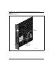
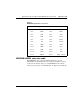
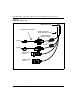
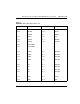
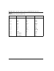
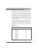
Table Of Contents
- Title Page
- Revision history
- Contents
- About this guide
- Description
- System requirements
- List of ITG ISDN components
- Ordering rules and guidelines
- ITG ISL Trunk card description
- ITG ISL Trunk card physical description
- ISDN Signaling Link
- Dialing plans
- Quality of Service
- Fallback to alternate facilities
- Type of Service
- Fax support
- Remote Access
- Per-call statistics support using RADIUS Client
- SNMP MIB
- Codec profiles
- Security passwords
- ITG Engineering Guidelines
- Introduction
- Network engineering guidelines overview
- ITG traffic engineering
- Configuration of Meridian 1 routes and network translation
- Assess WAN link resources
- QoS Evaluation Process Overview
- Set QoS
- Measure intranet QoS
- Implement QoS in IP networks
- ITG Trunk DSP profile settings
- Post-installation network measurements
- Estimate QoS level
- ITG MAT PC management configuration
- Install and configure ITG ISL Trunk node
- Before you begin
- Installation Procedure Summary
- Create the ITG Trunk Installation Summary Sheet
- Install and cable ITG trunk cards
- Install NTCW84JA Large System I/O Panel 50-Pin filter adapter
- Install NTMF94EA and NTCW84KA cables
- D-channel cabling for the NT0961AA 24-Port ITG Trunk card
- Set NT6D80 MSDL switches
- Install filter and NTND26 cable (for MSDL and DCHIP cards in same Large System equipment row)
- Install filter and NTND26 cable (for MSDL and DCHIP cards in different Large System equipment rows)
- Configure ITG Trunk data on the Meridian 1
- Configure dialing plans within the corporate network
- Configure ITG Trunk data on MAT
- Transmit ITG trunk card configuration data from MAT to the ITG trunk cards
- Set date and time for the ITG ISL Trunk node
- Change the default ITG shell password to maintain access security
- Change default ESN5 prefix for non-ESN5 IP telephony gateways
- Check card software
- Configure MAT Alarm Management to receive SNMP traps from ITG ISL Trunk cards
- Make test calls to the remote ITG nodes
- Upgrade an ITG Trunk 1.0 node to support ISDN signaling trunks
- Upgrade procedure summary
- Before you begin
- Install the DCHIP hardware upgrade kit
- Upgrade the 8-port ITG basic trunk software to ITG ISL trunk software
- Remove ITG 1.0 configuration data from Meridian 1
- Configure the Meridian 1 ITG ISL Trunk data: upgrade considerations
- Verify ROM-BIOS version
- Upgrade Troubleshooting
- OA&M using MAT applications
- OA&M using the ITG shell CLI and overlays
- Maintenance
- Appendix A: Calbe description and NT8D81BA cable replacement
- NTMF94EA E - LAN, T - LAN and Serial Port cable
- NTCW84KA E-LAN, T-LAN, DCH & Serial cable
- NTAG81CA Faceplate Maintenance cable
- NTAG81BA Maintenance Extender cable
- NTCW84EA DCH PC Card Pigtail cable
- NTMF04BA MSDL extension cable
- NTCW84LA and NTCW84MA upgrade cables
- Prevent ground loops on connection to external customer LAN equipment
- Replace cable NT8D81BA with NT8D81AA
- Tools list
- NT8D81BA cable removal procedures
- Appendix B: Environmental and electrical regulatory data
- Appendix C: Subnet mask conversion from CIDR to dotted decimal format
- Appendix D: Configure a Netgear RM356 modem router for remote access
- Index
- Back

Page 350 of
378
Appendix A: Cable description and NT8D81BA cable replacement
553-3001-202 Standard 1.00 April 2000
Replace cable NT8D81BA with NT8D81AA
This procedure explains how to replace the NT8D81BA cable with the
NT8D81AA cable and how to install the NTCW84JA special IPE filter.
Cables are designated by the letter of the I/O panel cutout (A, B, C, and so on)
where the 50-pin cable connector is attached. Each cable has three 20-pin
connectors (16 positions are used), designated 1, 2, and 3, that attach to the
backplane. Using the designations described, the backplane ends of the first
cable are referred to as A-1, A-2, and A-3. The locations of the cable
connectors on the backplane are designated by the slot number (L0 through
L9 for NT8D11, L0 through L15 for NT8D37) and the shroud row (1, 2, and
3). Using these designations, the slot positions in the first slot are referred to
as L0-1, L0-2, and L0-3.
In NT8D37BA and NT8D37EC (and later vintage) IPE Modules, all 16 IPE
card slots support 24-pair cable connections. Table 64 shows the cable
connections from the backplane to the inside of the I/O panel. Figure 65
shows the designations for the backplane end of the cables, the backplane slot
designations for the cable connections, and the associated network segments
for the backplane slots.
Table 64
NT8D37 cable connections
Backplane slots–shroud rows I/O panel/cable designation
L0–1, 2, 3
L1–1, 2, 3
L2–1, 2, 3
L3–1, 2, 3
L4–1, 2, 3
L5–1, 2, 3
L6–1, 2, 3
L7–1, 2, 3
L8–1, 2, 3
L9–1, 2, 3
L10–1, 2, 3
L11–1, 2, 3
L12–1, 2, 3
L13–1, 2, 3
L14–1, 2, 3
L15–1, 2, 3
A
B
C
D
E
F
G
H
K
L
M
N
R
S
T
U