
- LG Software Innovations Coffeemaker User Manual
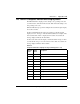
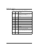
Table Of Contents
- Title Page
- Revision history
- Contents
- About this guide
- Description
- System requirements
- List of ITG ISDN components
- Ordering rules and guidelines
- ITG ISL Trunk card description
- ITG ISL Trunk card physical description
- ISDN Signaling Link
- Dialing plans
- Quality of Service
- Fallback to alternate facilities
- Type of Service
- Fax support
- Remote Access
- Per-call statistics support using RADIUS Client
- SNMP MIB
- Codec profiles
- Security passwords
- ITG Engineering Guidelines
- Introduction
- Network engineering guidelines overview
- ITG traffic engineering
- Configuration of Meridian 1 routes and network translation
- Assess WAN link resources
- QoS Evaluation Process Overview
- Set QoS
- Measure intranet QoS
- Implement QoS in IP networks
- ITG Trunk DSP profile settings
- Post-installation network measurements
- Estimate QoS level
- ITG MAT PC management configuration
- Install and configure ITG ISL Trunk node
- Before you begin
- Installation Procedure Summary
- Create the ITG Trunk Installation Summary Sheet
- Install and cable ITG trunk cards
- Install NTCW84JA Large System I/O Panel 50-Pin filter adapter
- Install NTMF94EA and NTCW84KA cables
- D-channel cabling for the NT0961AA 24-Port ITG Trunk card
- Set NT6D80 MSDL switches
- Install filter and NTND26 cable (for MSDL and DCHIP cards in same Large System equipment row)
- Install filter and NTND26 cable (for MSDL and DCHIP cards in different Large System equipment rows)
- Configure ITG Trunk data on the Meridian 1
- Configure dialing plans within the corporate network
- Configure ITG Trunk data on MAT
- Transmit ITG trunk card configuration data from MAT to the ITG trunk cards
- Set date and time for the ITG ISL Trunk node
- Change the default ITG shell password to maintain access security
- Change default ESN5 prefix for non-ESN5 IP telephony gateways
- Check card software
- Configure MAT Alarm Management to receive SNMP traps from ITG ISL Trunk cards
- Make test calls to the remote ITG nodes
- Upgrade an ITG Trunk 1.0 node to support ISDN signaling trunks
- Upgrade procedure summary
- Before you begin
- Install the DCHIP hardware upgrade kit
- Upgrade the 8-port ITG basic trunk software to ITG ISL trunk software
- Remove ITG 1.0 configuration data from Meridian 1
- Configure the Meridian 1 ITG ISL Trunk data: upgrade considerations
- Verify ROM-BIOS version
- Upgrade Troubleshooting
- OA&M using MAT applications
- OA&M using the ITG shell CLI and overlays
- Maintenance
- Appendix A: Calbe description and NT8D81BA cable replacement
- NTMF94EA E - LAN, T - LAN and Serial Port cable
- NTCW84KA E-LAN, T-LAN, DCH & Serial cable
- NTAG81CA Faceplate Maintenance cable
- NTAG81BA Maintenance Extender cable
- NTCW84EA DCH PC Card Pigtail cable
- NTMF04BA MSDL extension cable
- NTCW84LA and NTCW84MA upgrade cables
- Prevent ground loops on connection to external customer LAN equipment
- Replace cable NT8D81BA with NT8D81AA
- Tools list
- NT8D81BA cable removal procedures
- Appendix B: Environmental and electrical regulatory data
- Appendix C: Subnet mask conversion from CIDR to dotted decimal format
- Appendix D: Configure a Netgear RM356 modem router for remote access
- Index
- Back
Maintenance Page 329 of 378
ITG Trunk 2.0 ISDN Signaling Link (ISL) Description, Installation and Operation
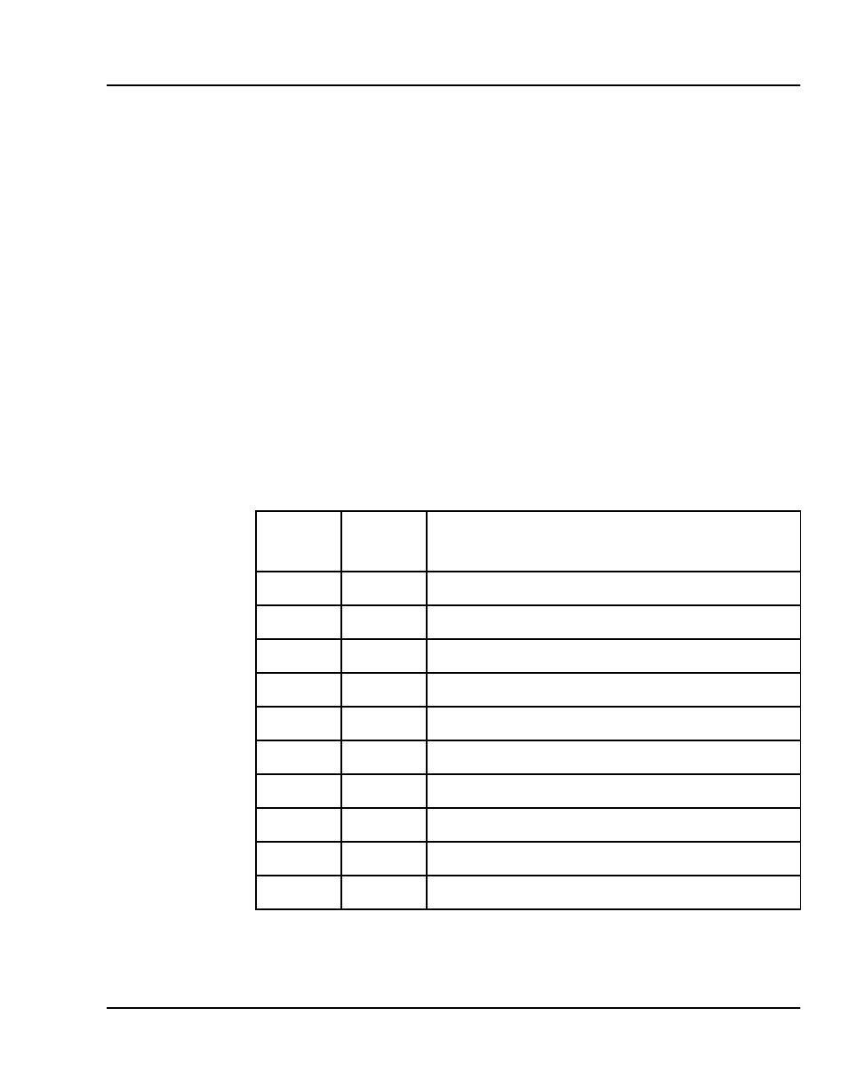
ITG Trunk 2.0 faceplate maintenance display codes
The ITG maintenance display provides startup codes, operating mode and
error information on the functional card state. Table 56 lists the startup codes
and operating mode codes.
When the ITG starts up, it performs multiple self-tests. The faceplate display
shows the test results.
If self-tests T:00-T:09 fail, the self-test program stops and the faceplate
displays an “F:xx” message to indicate which test failed. For example, if the
timer test T:05 fails, “F:05” is displayed. If more than one test fails, the
message displayed indicates the first failure.
If self-tests T:10-T:17 fail, the display contains the failure message for three
seconds and the card goes on to the next test. If more than one test fails, the
message displayed indicates the last failure.
Table 56
Faceplate maintenance display message summary (Part 1 of 4)
Normal
Code
Fault
Code
Description
T:00 F:00 Initialization
T:01 F:01 Testing Internal RAM
T:02 F:02 Testing ALU
T:03 F:03 Testing address modes
T:04 F:04 Testing Boot ROM
T:05 F:05 Testing timers
T:06 F:06 Testing watchdog
T:07 F:07 Testing external RAM
T:08 F:08 Testing Host DPRAM
T:09 F:09 Testing DS30 DPRAM