
- LG Software Innovations Coffeemaker User Manual
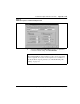
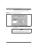
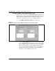
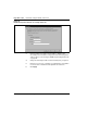
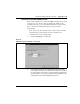
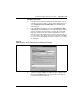
Table Of Contents
- Title Page
- Revision history
- Contents
- About this guide
- Description
- System requirements
- List of ITG ISDN components
- Ordering rules and guidelines
- ITG ISL Trunk card description
- ITG ISL Trunk card physical description
- ISDN Signaling Link
- Dialing plans
- Quality of Service
- Fallback to alternate facilities
- Type of Service
- Fax support
- Remote Access
- Per-call statistics support using RADIUS Client
- SNMP MIB
- Codec profiles
- Security passwords
- ITG Engineering Guidelines
- Introduction
- Network engineering guidelines overview
- ITG traffic engineering
- Configuration of Meridian 1 routes and network translation
- Assess WAN link resources
- QoS Evaluation Process Overview
- Set QoS
- Measure intranet QoS
- Implement QoS in IP networks
- ITG Trunk DSP profile settings
- Post-installation network measurements
- Estimate QoS level
- ITG MAT PC management configuration
- Install and configure ITG ISL Trunk node
- Before you begin
- Installation Procedure Summary
- Create the ITG Trunk Installation Summary Sheet
- Install and cable ITG trunk cards
- Install NTCW84JA Large System I/O Panel 50-Pin filter adapter
- Install NTMF94EA and NTCW84KA cables
- D-channel cabling for the NT0961AA 24-Port ITG Trunk card
- Set NT6D80 MSDL switches
- Install filter and NTND26 cable (for MSDL and DCHIP cards in same Large System equipment row)
- Install filter and NTND26 cable (for MSDL and DCHIP cards in different Large System equipment rows)
- Configure ITG Trunk data on the Meridian 1
- Configure dialing plans within the corporate network
- Configure ITG Trunk data on MAT
- Transmit ITG trunk card configuration data from MAT to the ITG trunk cards
- Set date and time for the ITG ISL Trunk node
- Change the default ITG shell password to maintain access security
- Change default ESN5 prefix for non-ESN5 IP telephony gateways
- Check card software
- Configure MAT Alarm Management to receive SNMP traps from ITG ISL Trunk cards
- Make test calls to the remote ITG nodes
- Upgrade an ITG Trunk 1.0 node to support ISDN signaling trunks
- Upgrade procedure summary
- Before you begin
- Install the DCHIP hardware upgrade kit
- Upgrade the 8-port ITG basic trunk software to ITG ISL trunk software
- Remove ITG 1.0 configuration data from Meridian 1
- Configure the Meridian 1 ITG ISL Trunk data: upgrade considerations
- Verify ROM-BIOS version
- Upgrade Troubleshooting
- OA&M using MAT applications
- OA&M using the ITG shell CLI and overlays
- Maintenance
- Appendix A: Calbe description and NT8D81BA cable replacement
- NTMF94EA E - LAN, T - LAN and Serial Port cable
- NTCW84KA E-LAN, T-LAN, DCH & Serial cable
- NTAG81CA Faceplate Maintenance cable
- NTAG81BA Maintenance Extender cable
- NTCW84EA DCH PC Card Pigtail cable
- NTMF04BA MSDL extension cable
- NTCW84LA and NTCW84MA upgrade cables
- Prevent ground loops on connection to external customer LAN equipment
- Replace cable NT8D81BA with NT8D81AA
- Tools list
- NT8D81BA cable removal procedures
- Appendix B: Environmental and electrical regulatory data
- Appendix C: Subnet mask conversion from CIDR to dotted decimal format
- Appendix D: Configure a Netgear RM356 modem router for remote access
- Index
- Back

Page 210 of
378
Install and configure ITG ISL Trunk node
553-3001-202 Standard 1.00 April 2000
4 Define Node capability for the destination node.
The default setting is SL1, which supports MCDN features. The Node
capability field defines the D-channel protocol used by the destination
ITG ISL Trunk node. The protocol must match the protocol configured
in LD16 in the route data block at the IFC prompt with respect to SL1
vs. ESGF or ISGF QSIG interface (IFC) and in LD17 at the IFC prompt
under ADAN DCH. In LD 16, if SIGO is set to STD, then you must
select the SL1 node capability. If SIGO is set to ESN5, then you must
select SL1ESN5 node capability. In a mixed ESN5 and non-ESN5
network, you must configure an ESN5 prefix for the non-ESN5 IP
telephony gateways by using the “esn5PrefixSet” command from the
ITG shell CLI. See “Change default ESN5 prefix for non-ESN5 IP
telephony gateways” on page 223.
The choices are SL1, SL1 ESN5, ESIG and ISIG for networks
consisting of Meridian 1 large systems. For networks that include
Meridian 1 small systems, the choices are SL1 or SL1 ESN5.
In addition to ITG ISL Trunk nodes, the IP telephony trunk network may
contain ITG Trunk 1.0 Basic Trunk nodes or Nortel Networks IP
Telephony Connection Manager. Use H323 V2 node capability for
these nodes.
Qualit
y
of service
The default setting enables Quality of Service monitoring. QoS
monitoring allows new calls to fall back to alternate circuit switched
trunk routes when the IP network Quality of Service falls below the
configured threshold. If you change the default setting and disable
QoS monitoring, then the ITG trunk node attempts to complete new
calls over the IP network regardless of the IP network QoS. You can
still have alternate routes but ITG Trunk only uses them if the
D-Channel connection to the local ITG Trunk node fails, or if the
destination node fails to respond, or if the destination node responds
that all trunks are busy.
5 To disable QoS monitoring of a destination node, uncheck the Enable
Quality of Service (QoS) monitoring checkbox.
6 Slide the Quality of Service control bar to set the QoS level. The default
setting is 3 (=Good).
See “E-Model” on page 56 and Table 24, “ITG QoS levels,” on
page 143 for more details on Quality of Service levels and MOS
values.