
- LG Software Innovations Coffeemaker User Manual
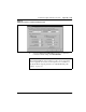
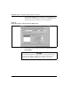
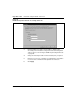
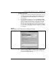
Table Of Contents
- Title Page
- Revision history
- Contents
- About this guide
- Description
- System requirements
- List of ITG ISDN components
- Ordering rules and guidelines
- ITG ISL Trunk card description
- ITG ISL Trunk card physical description
- ISDN Signaling Link
- Dialing plans
- Quality of Service
- Fallback to alternate facilities
- Type of Service
- Fax support
- Remote Access
- Per-call statistics support using RADIUS Client
- SNMP MIB
- Codec profiles
- Security passwords
- ITG Engineering Guidelines
- Introduction
- Network engineering guidelines overview
- ITG traffic engineering
- Configuration of Meridian 1 routes and network translation
- Assess WAN link resources
- QoS Evaluation Process Overview
- Set QoS
- Measure intranet QoS
- Implement QoS in IP networks
- ITG Trunk DSP profile settings
- Post-installation network measurements
- Estimate QoS level
- ITG MAT PC management configuration
- Install and configure ITG ISL Trunk node
- Before you begin
- Installation Procedure Summary
- Create the ITG Trunk Installation Summary Sheet
- Install and cable ITG trunk cards
- Install NTCW84JA Large System I/O Panel 50-Pin filter adapter
- Install NTMF94EA and NTCW84KA cables
- D-channel cabling for the NT0961AA 24-Port ITG Trunk card
- Set NT6D80 MSDL switches
- Install filter and NTND26 cable (for MSDL and DCHIP cards in same Large System equipment row)
- Install filter and NTND26 cable (for MSDL and DCHIP cards in different Large System equipment rows)
- Configure ITG Trunk data on the Meridian 1
- Configure dialing plans within the corporate network
- Configure ITG Trunk data on MAT
- Transmit ITG trunk card configuration data from MAT to the ITG trunk cards
- Set date and time for the ITG ISL Trunk node
- Change the default ITG shell password to maintain access security
- Change default ESN5 prefix for non-ESN5 IP telephony gateways
- Check card software
- Configure MAT Alarm Management to receive SNMP traps from ITG ISL Trunk cards
- Make test calls to the remote ITG nodes
- Upgrade an ITG Trunk 1.0 node to support ISDN signaling trunks
- Upgrade procedure summary
- Before you begin
- Install the DCHIP hardware upgrade kit
- Upgrade the 8-port ITG basic trunk software to ITG ISL trunk software
- Remove ITG 1.0 configuration data from Meridian 1
- Configure the Meridian 1 ITG ISL Trunk data: upgrade considerations
- Verify ROM-BIOS version
- Upgrade Troubleshooting
- OA&M using MAT applications
- OA&M using the ITG shell CLI and overlays
- Maintenance
- Appendix A: Calbe description and NT8D81BA cable replacement
- NTMF94EA E - LAN, T - LAN and Serial Port cable
- NTCW84KA E-LAN, T-LAN, DCH & Serial cable
- NTAG81CA Faceplate Maintenance cable
- NTAG81BA Maintenance Extender cable
- NTCW84EA DCH PC Card Pigtail cable
- NTMF04BA MSDL extension cable
- NTCW84LA and NTCW84MA upgrade cables
- Prevent ground loops on connection to external customer LAN equipment
- Replace cable NT8D81BA with NT8D81AA
- Tools list
- NT8D81BA cable removal procedures
- Appendix B: Environmental and electrical regulatory data
- Appendix C: Subnet mask conversion from CIDR to dotted decimal format
- Appendix D: Configure a Netgear RM356 modem router for remote access
- Index
- Back

Page 208 of
378
Install and configure ITG ISL Trunk node
553-3001-202 Standard 1.00 April 2000
Exit node property configuration session
The procedure to add an ITG Trunk node on MAT manually is complete.
Press OK to save the node and card properties configuration and exit. MAT
displays the IP Telephony Gateway - ISDN IP Trunk Main window. If you
plan to manage a network of ITG ISL Trunk nodes from this MAT PC, add
the remaining ITG ISL Trunk nodes before you configure the dialing plan for
the new ITG Trunk nodes on MAT.
Create the ITG Trunk node dialing plan using MAT
In this procedure, you configure the ITG Trunk node dialing plan in MAT.
Use this procedure to create the dialing plan for the first node in the network.
This procedure will also work to create a dialing plan for a new node in a very
small network. If you are adding a new node to a large existing network, it is
more efficient to retrieve the ITG Trunk node dialing plan from an existing
node. See “Retrieve the ITG Trunk node dialing plan using MAT” on
page 213.
A dialing plan consists of a number of ITG Trunk destination nodes and one
or more dialing plan entries for each destination node. You select a
destination node, define the destination node protocol capability, decide if
you want to enable Quality of Service (QoS) monitoring for this destination
node, and enter one or more ESN dialing plan entries for each destination
node. You repeat this procedure for all destination nodes in the ITG Trunk
network.
The dialing plan information you enter in MAT must match the ESN data
entered in the Meridian 1 overlays (LD15, LD16, LD86, LD87 and LD90).
You must keep the dialing plan entries consistent between the Meridian 1 and
the ITG Trunk node. Transmit the dialing plan from MAT ITG to the ITG
Trunk node during installation, card replacement, when ITG Trunk nodes are
added to the network, or whenever you change the dialing plan on MAT ITG.
Each ITG Trunk node shares one dialing plan for all cards in the node. The
ITG Trunk node dialing plan translates the dialed digits in the Meridian 1
ISDN Signaling Call Setup message, according to ESN translation type, into
the Node IP addresses of the ITG Trunk destination nodes.