
- LG Software Innovations Coffeemaker User Manual
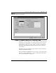
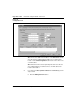
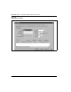
Table Of Contents
- Title Page
- Revision history
- Contents
- About this guide
- Description
- System requirements
- List of ITG ISDN components
- Ordering rules and guidelines
- ITG ISL Trunk card description
- ITG ISL Trunk card physical description
- ISDN Signaling Link
- Dialing plans
- Quality of Service
- Fallback to alternate facilities
- Type of Service
- Fax support
- Remote Access
- Per-call statistics support using RADIUS Client
- SNMP MIB
- Codec profiles
- Security passwords
- ITG Engineering Guidelines
- Introduction
- Network engineering guidelines overview
- ITG traffic engineering
- Configuration of Meridian 1 routes and network translation
- Assess WAN link resources
- QoS Evaluation Process Overview
- Set QoS
- Measure intranet QoS
- Implement QoS in IP networks
- ITG Trunk DSP profile settings
- Post-installation network measurements
- Estimate QoS level
- ITG MAT PC management configuration
- Install and configure ITG ISL Trunk node
- Before you begin
- Installation Procedure Summary
- Create the ITG Trunk Installation Summary Sheet
- Install and cable ITG trunk cards
- Install NTCW84JA Large System I/O Panel 50-Pin filter adapter
- Install NTMF94EA and NTCW84KA cables
- D-channel cabling for the NT0961AA 24-Port ITG Trunk card
- Set NT6D80 MSDL switches
- Install filter and NTND26 cable (for MSDL and DCHIP cards in same Large System equipment row)
- Install filter and NTND26 cable (for MSDL and DCHIP cards in different Large System equipment rows)
- Configure ITG Trunk data on the Meridian 1
- Configure dialing plans within the corporate network
- Configure ITG Trunk data on MAT
- Transmit ITG trunk card configuration data from MAT to the ITG trunk cards
- Set date and time for the ITG ISL Trunk node
- Change the default ITG shell password to maintain access security
- Change default ESN5 prefix for non-ESN5 IP telephony gateways
- Check card software
- Configure MAT Alarm Management to receive SNMP traps from ITG ISL Trunk cards
- Make test calls to the remote ITG nodes
- Upgrade an ITG Trunk 1.0 node to support ISDN signaling trunks
- Upgrade procedure summary
- Before you begin
- Install the DCHIP hardware upgrade kit
- Upgrade the 8-port ITG basic trunk software to ITG ISL trunk software
- Remove ITG 1.0 configuration data from Meridian 1
- Configure the Meridian 1 ITG ISL Trunk data: upgrade considerations
- Verify ROM-BIOS version
- Upgrade Troubleshooting
- OA&M using MAT applications
- OA&M using the ITG shell CLI and overlays
- Maintenance
- Appendix A: Calbe description and NT8D81BA cable replacement
- NTMF94EA E - LAN, T - LAN and Serial Port cable
- NTCW84KA E-LAN, T-LAN, DCH & Serial cable
- NTAG81CA Faceplate Maintenance cable
- NTAG81BA Maintenance Extender cable
- NTCW84EA DCH PC Card Pigtail cable
- NTMF04BA MSDL extension cable
- NTCW84LA and NTCW84MA upgrade cables
- Prevent ground loops on connection to external customer LAN equipment
- Replace cable NT8D81BA with NT8D81AA
- Tools list
- NT8D81BA cable removal procedures
- Appendix B: Environmental and electrical regulatory data
- Appendix C: Subnet mask conversion from CIDR to dotted decimal format
- Appendix D: Configure a Netgear RM356 modem router for remote access
- Index
- Back

Install and configure ITG ISL Trunk node Page 195 of
378
ITG Trunk 2.0 ISDN Signaling Link (ISL) Description, Installation and Operation
Configure card properties
These procedures explain how to configure the ITG ISL trunk card roles, IP
addresses, TN, card density and D-Channel settings. Each ITG ISL Trunk
node requires a Leader 0 card and one DCHIP card (which can be Leader 0),
and can have a Leader 1 card, one or more Follower cards, and additional
DCHIP cards (which can be Leader 1 or Follower cards). Either Leader 0 or
Leader 1 can have the Active Leader status. On system power-up, Leader 0
normally functions as the Active Leader and Leader 1 as the Backup Leader.
At other times, the Leader card functions can reverse with Leader 1 working
as the Active Leader and Leader 0 working as the Backup Leader. To add an
ITG card to the node, perform the following steps:
1 From the General tab, click the Configuration tab. If you selected the
single subnet option in the General tab, the Voice IP and Voice LAN
gateway IP fields will be greyed-out.
2 Select the Card role from the drop-down list box:
When you add the first card, select the card role Leader 0. When you
add the second card, select the card type Leader 1. When you add
additional cards, select the card type Follower. You configure the
DCHIP and D-Channel information.
3 If you checked Use separate subnets in the General tab, perform
steps a-d.
a Enter the Management IP address.
b Enter the Management MAC address. It is the motherboard
Ethernet address. You can find it on the faceplate label of the card
you are currently configuring. It is also identified as lnIsa0 on the
card startup messages and by the ifShow command in the ITG
shell.
c Enter Voice IP address (see Notes 1 and 2).
d Enter Voice LAN gateway IP address (see Notes 1 and 2).