
- LG Software Innovations Coffeemaker User Manual
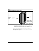
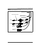
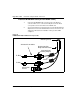
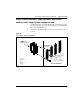
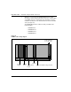
Table Of Contents
- Title Page
- Revision history
- Contents
- About this guide
- Description
- System requirements
- List of ITG ISDN components
- Ordering rules and guidelines
- ITG ISL Trunk card description
- ITG ISL Trunk card physical description
- ISDN Signaling Link
- Dialing plans
- Quality of Service
- Fallback to alternate facilities
- Type of Service
- Fax support
- Remote Access
- Per-call statistics support using RADIUS Client
- SNMP MIB
- Codec profiles
- Security passwords
- ITG Engineering Guidelines
- Introduction
- Network engineering guidelines overview
- ITG traffic engineering
- Configuration of Meridian 1 routes and network translation
- Assess WAN link resources
- QoS Evaluation Process Overview
- Set QoS
- Measure intranet QoS
- Implement QoS in IP networks
- ITG Trunk DSP profile settings
- Post-installation network measurements
- Estimate QoS level
- ITG MAT PC management configuration
- Install and configure ITG ISL Trunk node
- Before you begin
- Installation Procedure Summary
- Create the ITG Trunk Installation Summary Sheet
- Install and cable ITG trunk cards
- Install NTCW84JA Large System I/O Panel 50-Pin filter adapter
- Install NTMF94EA and NTCW84KA cables
- D-channel cabling for the NT0961AA 24-Port ITG Trunk card
- Set NT6D80 MSDL switches
- Install filter and NTND26 cable (for MSDL and DCHIP cards in same Large System equipment row)
- Install filter and NTND26 cable (for MSDL and DCHIP cards in different Large System equipment rows)
- Configure ITG Trunk data on the Meridian 1
- Configure dialing plans within the corporate network
- Configure ITG Trunk data on MAT
- Transmit ITG trunk card configuration data from MAT to the ITG trunk cards
- Set date and time for the ITG ISL Trunk node
- Change the default ITG shell password to maintain access security
- Change default ESN5 prefix for non-ESN5 IP telephony gateways
- Check card software
- Configure MAT Alarm Management to receive SNMP traps from ITG ISL Trunk cards
- Make test calls to the remote ITG nodes
- Upgrade an ITG Trunk 1.0 node to support ISDN signaling trunks
- Upgrade procedure summary
- Before you begin
- Install the DCHIP hardware upgrade kit
- Upgrade the 8-port ITG basic trunk software to ITG ISL trunk software
- Remove ITG 1.0 configuration data from Meridian 1
- Configure the Meridian 1 ITG ISL Trunk data: upgrade considerations
- Verify ROM-BIOS version
- Upgrade Troubleshooting
- OA&M using MAT applications
- OA&M using the ITG shell CLI and overlays
- Maintenance
- Appendix A: Calbe description and NT8D81BA cable replacement
- NTMF94EA E - LAN, T - LAN and Serial Port cable
- NTCW84KA E-LAN, T-LAN, DCH & Serial cable
- NTAG81CA Faceplate Maintenance cable
- NTAG81BA Maintenance Extender cable
- NTCW84EA DCH PC Card Pigtail cable
- NTMF04BA MSDL extension cable
- NTCW84LA and NTCW84MA upgrade cables
- Prevent ground loops on connection to external customer LAN equipment
- Replace cable NT8D81BA with NT8D81AA
- Tools list
- NT8D81BA cable removal procedures
- Appendix B: Environmental and electrical regulatory data
- Appendix C: Subnet mask conversion from CIDR to dotted decimal format
- Appendix D: Configure a Netgear RM356 modem router for remote access
- Index
- Back

Page 162 of
378
Install and configure ITG ISL Trunk node
553-3001-202 Standard 1.00 April 2000
Note: The NTCW84JA filter connector is required for separate subnets
using 100BaseTX for the T-LAN connection.
Remove existing I/O panel filter adapter
The standard I/O filter adapter is shielded metal with a black plastic insert
connector. The NTCW84JA adapter uses yellow warning labels to indicate
EMC filtering modifications and which MDF connection points can support
100BaseT connection.
1 Before any of the following installation steps, remove the ITG pack, or
any other IPE pack, from the IPE shelf card slot corresponding to the
I/O Panel connector to be removed.
Note:
Make sure to use the I/O panel connector which corresponds to
the left slot number of the DCHIP card.
2 First remove the NT8D81AA Backplane to I/O Panel ribbon cable
assembly which will be connected to the backplane side of the existing
block by releasing the latching pins on the filter block and pulling the
NT8D81AA cable away.
3 Next unscrew the existing filter adapter from the I/O panel. There is
one screw on the lower front of the adapter and one screw on the
upper back of the adapter. Remove the adapter.
4 Re-position the new NTCW84JA filter adapter in the now vacant I/O
panel opening. (See Figure 22 on page 160.)
5 Attach the new NTCW84JA to the I/O panel by securely fastening the
top back screw and the bottom front screw.
6 Reconnect the NT8D81AA cable and secure it in place by snapping
shut the locking latches provided on the NTCW84JA connector.